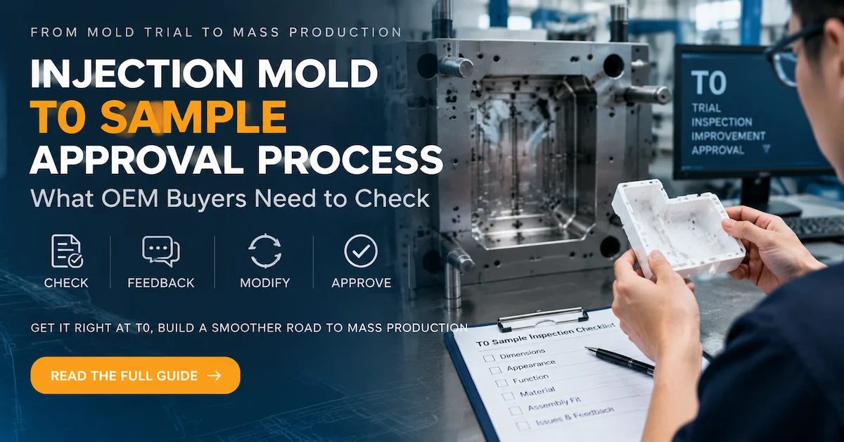
Injection Mold T0 Sample Approval Process: What OEM Buyers Need to Check
For an OEM injection molding project, the first molded samples are not simply samples to look at and approve. A t0 mold trial is an engineering checkpoint where the buyer and mold supplier compare the physical part against the approved product requirements, identify defects, determine what needs to change, and establish what the next trial must prove.
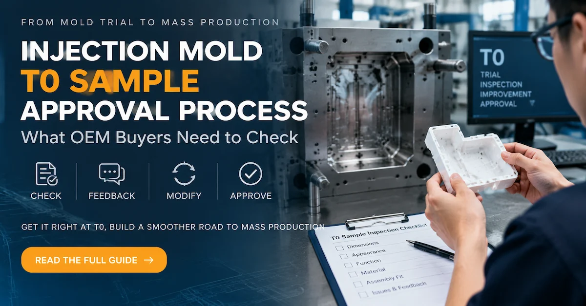
The most useful way to manage T0 and T1 is as a controlled loop:
1. What Is a T0 Mold Trial?
A t0 mold trial is the initial trial molding stage used to evaluate a newly manufactured injection mold and the molded parts it produces. The exact meaning of T0 can vary between companies, so OEM buyers should not rely on the label alone. The important question is what the trial is intended to prove.
At T0, the engineering team receives the first physical evidence of how the tooling behaves with the intended product geometry and molding material. The trial can reveal issues that were difficult to identify from CAD data or mold design alone.
Typical T0 findings include:
- Short shots or incomplete filling
- Flash around the parting line or shut-off areas
- Sink marks around thick sections, bosses or ribs
- Weld lines and flow-related cosmetic problems
- Burn marks or trapped-air indications
- Ejector marks or difficulty releasing the part
- Warpage or distortion
- Critical dimensions outside the agreed tolerance
- Incorrect hole, boss or connector positions
- Assembly interference
- Variation between cavities in multi-cavity tooling
The purpose of T0 is therefore not simply to ask, “Does the sample look good?” A better question is, “What does this trial tell us about the mold, the molded part, and the remaining production risks?”
2. What Should Be Confirmed Before the T0 Trial?
A weak approval process begins with unclear requirements. If the buyer and supplier do not use the same product drawing, material, revision or acceptance criteria, even a technically accurate inspection can lead to disagreement.
Before the first trial, confirm the following project inputs:
| Project input | What the OEM buyer should confirm | Why it matters |
|---|---|---|
| Product definition | Current 2D drawing, 3D CAD and revision | Prevents evaluation against obsolete geometry |
| Material | Plastic resin and grade where specified | Material behavior can influence molding and dimensions |
| Critical dimensions | CTQs, datums and tolerances | Defines what must be measured |
| Appearance | Visible areas, texture and cosmetic limits | Prevents subjective appearance approval |
| Assembly | Mating components and functional interfaces | Shows whether the molded part works in the product |
| Sampling | Sample quantity and cavity identification | Allows representative evaluation |
| Inspection | Measurement method and conditions | Makes results repeatable |
This preparation is particularly important for precision plastic parts. ISO 20457:2026 provides a plastics-specific framework for dimensional and geometrical tolerances and acceptance conditions. Plastic parts can behave differently from rigid metal components because shrinkage, material behavior, processing conditions, cooling and warpage can affect the final geometry.
The buyer should therefore distinguish between functionally necessary tolerance and a tolerance that is simply copied from another component. Overly tight requirements can make a molded part unnecessarily difficult or expensive to manufacture, while overly loose requirements can create assembly or functional problems.
3. What Information Should Be Recorded During a T0 Mold Trial?
A professional T0 mold trial should generate traceable information. Photographs alone are not enough for an OEM project because they cannot explain the exact material, cavity, drawing revision or measurement condition associated with a sample.
| Trial record | Recommended information |
|---|---|
| Tool identity | Mold name, project number and mold revision |
| Product identity | Part number and drawing revision |
| Material | Resin type and grade used for the trial |
| Machine | Injection machine information where relevant |
| Cavity | Cavity number for multi-cavity molds |
| Samples | Sample identification and quantity |
| Dimensions | Measured CTQs and inspection method |
| Appearance | Defect type, location and photographs |
| Assembly | Fit, interference and functional observations |
| Open issues | Problem description and corrective-action requirement |
For multi-cavity molds, cavity identification becomes especially important. If cavity 1 produces an acceptable part while cavity 2 produces a dimensional problem, the correct engineering response is different from a defect that appears in every cavity.
A buyer should also avoid mixing samples from different trial conditions without labeling them. Otherwise, a later measurement may appear inconsistent simply because the samples were produced under different conditions.
4. Dimensional Inspection: Which Measurements Matter Most?
An OEM buyer does not necessarily need to measure every dimension with equal priority. The inspection plan should focus on dimensions that control function, assembly, sealing, alignment, movement or another defined product requirement.
Typical critical-to-quality dimensions may include:
- Mounting-hole diameter and position
- Boss diameter and height
- Connector openings
- Overall dimensions that control assembly
- Sealing surfaces
- Snap-fit features
- Datum-to-feature relationships
- Wall thickness in critical areas
- Moving clearances
- Interfaces with metal, electronic or molded components
The measurement method should match the feature. Straightforward dimensions may be checked using appropriate calibrated measurement equipment, while complex profiles or positional relationships may require more advanced inspection methods.
More important than producing a large inspection report is creating a report that can answer three questions:
- What requirement was checked?
- What result was measured?
- Does the result affect product function or assembly?
For plastic molded parts, measurement conditions also matter. Temperature, conditioning, shrinkage and warpage can affect results. If the buyer measures the sample immediately while the supplier measures it later under different conditions, the two parties may obtain different results without either measurement being technically careless.
This is why the inspection method and timing should be agreed before T0 rather than debated after a dimensional disagreement occurs.
5. Appearance Inspection: Do Not Approve a Sample With “Looks Good”
Appearance is one of the most common sources of disagreement during a t0 mold trial. Buyers may describe a surface as unacceptable while the supplier considers the same condition normal unless a specific cosmetic standard has been defined.
Common molding defects include:
- Flash
- Short shot
- Sink marks
- Weld lines
- Flow marks
- Burn marks
- Ejector marks
- Gate marks
- Drag marks
- Surface-texture variation
- Warpage
The location of a defect is often as important as the defect itself. A small gate mark on a hidden surface may have a different commercial impact from the same mark on the main visible face. Similarly, a weld line in a non-functional area may be primarily cosmetic, while a defect at a sealing or structural interface may require a different response.
A practical inspection system can divide the part into:
| Inspection zone | Buyer focus |
|---|---|
| Critical cosmetic area | Visible defects, texture, gloss, color and surface consistency |
| Functional area | Defects that may affect operation or strength |
| Assembly area | Flash, deformation or geometry that may affect mating components |
| Hidden/non-critical area | Defects evaluated against the agreed cosmetic standard |
Marked photographs are particularly useful. Instead of writing “surface needs improvement,” identify the location, defect type and expected T1 condition.
6. Why Assembly Verification Should Be Included in T0 Approval
A molded component is not always useful simply because it passes isolated dimensional inspection. Many OEM parts are designed to interact with other components, and the actual product interface may reveal problems that are not obvious from the plastic part alone.
Where applicable, T0 approval should include checks such as:
- Fit with mating parts
- Screw and fastener alignment
- Snap-fit engagement
- Connector access
- Cover closure
- Seal contact
- Moving-part clearance
- PCB or insert positioning
Consider a plastic housing with a PCB mounting boss. The boss diameter may be within tolerance, but its position could still prevent the PCB from aligning with another connector. Measuring the boss alone would miss the actual product problem.
This is why assembly validation should be connected to the product function, not treated as an optional cosmetic check.
7. How Should OEM Buyers Classify T0 Problems?
One of the most important steps after a T0 mold trial is determining what kind of problem has actually occurred. Not every defect should immediately result in cutting steel.
A molding problem can originate from several areas:
- Product design
- Mold design
- Mold manufacturing
- Material
- Molding process
- Measurement method
- Assembly tolerance relationship
| T0 finding | Possible areas to investigate | Typical corrective direction |
|---|---|---|
| Flash | Parting surface, shut-off, fitting, pressure, geometry | Determine whether the issue is tooling or molding condition |
| Short shot | Flow path, gate, venting, temperature, pressure | Identify the filling restriction before modifying steel |
| Sink mark | Wall thickness, ribs, bosses, packing, cooling | Review geometry, cooling and process together |
| Warpage | Geometry, shrinkage, cooling, packing, ejection | Separate design, tooling and process contributions |
| Weld line | Flow fronts, gate location, venting, process | Review flow path and venting strategy |
| Ejection mark | Draft, ejection layout, sticking, cooling | Review release and ejection conditions |
| Dimension deviation | Shrinkage, tooling geometry, material, process | Determine whether the variation is tool- or process-related |
| Assembly interference | Feature location, tolerance stack, warpage | Review the complete interface |
| Cavity variation | Runner balance, gate, cooling, cavity geometry | Compare affected cavities individually |
This table should be treated as a diagnostic framework rather than an automatic diagnosis. The objective is to stop the team from making random modifications based on symptoms alone.
8. How to Write Useful T0 Problem Feedback
The quality of the feedback determines how efficiently the supplier can respond. Comments such as “please improve the sample” or “dimension is not good” create another round of questions instead of a corrective-action target.
A useful T0 feedback item should contain:
- Problem: What is wrong?
- Location: Where is it located?
- Requirement: Which drawing, specification or standard applies?
- Evidence: What measurement, photograph or assembly result supports the finding?
- Impact: Why does it matter?
- Action: What needs to be investigated or corrected?
- T1 target: What must the next trial demonstrate?
| Weak feedback | Better feedback |
|---|---|
| “Boss is wrong.” | “Mounting boss position is outside the approved drawing tolerance. Please review the tooling/process cause and verify the same feature during T1.” |
| “Surface needs improvement.” | “Flow mark is visible on the designated cosmetic zone. Please review the molding/tooling cause and submit the same area for T1 appearance verification.” |
| “Part does not fit.” | “Part interferes with the mating component at the marked interface. Please check feature position and repeat the assembly check at T1.” |
| “Flash is too much.” | “Flash is present along the marked shut-off area and affects assembly. Review the tooling condition and verify the same location after correction.” |
This approach converts subjective feedback into an engineering action list. It also creates a record that can be used later to determine whether T1 actually solved the original problem.
9. Separate Supplier Corrections From Customer Design Changes
This distinction is essential for both technical and commercial control.
If the approved product drawing has not changed and the molded part does not meet the agreed requirement, the issue may be a tooling, process or manufacturing correction. If the buyer changes the product geometry, tolerance, material or cosmetic requirement after T0, that is an engineering change rather than simply a supplier correction.
The project record should therefore identify:
- Original requirement
- Current product revision
- Original T0 result
- Customer-requested change, if any
- Supplier corrective action
- Tool modification
- T1 verification result
Without revision control, the supplier may correct the mold according to one drawing while the buyer evaluates the T1 sample against another. That creates unnecessary delays and makes responsibility difficult to determine.
10. How Should the Mold Modification Process Work After T0?
Once the problems are classified, the next step is a controlled modification plan. The supplier should understand which issue is being corrected, which tooling area may be affected, and what result the T1 trial is expected to demonstrate.
| Modification record | Information to document |
|---|---|
| Issue reference | Link the modification to the original T0 problem |
| Affected area | Cavity, core, insert, slide, lifter, gate, vent or other area |
| Cause direction | Engineering explanation or working hypothesis |
| Modification | Describe the planned tooling or process correction |
| Expected result | Define what the T1 sample must demonstrate |
| Risk to other features | Consider whether the change can affect dimensions or appearance elsewhere |
| Verification | Define measurement, appearance or assembly checks |
Not every T0 problem requires a tooling modification. Some problems may be related to process conditions. Others may require product-design review. The important principle is to identify the cause before choosing the correction.
For example, if a dimension is outside tolerance, increasing or reducing a tooling feature may appear to solve the problem, but if the actual cause is material shrinkage or process variation, the modification may not produce a stable result.
Similarly, if a product has a deep undercut that creates ejection problems, the engineering solution could involve a tooling mechanism, a product-design change, or another manufacturing approach depending on the product requirement.
11. What Should T1 Prove?
The purpose of T1 should be clearly connected to the T0 feedback. T1 is not successful simply because it is labeled “T1.” The trial should provide evidence that the agreed corrective actions have achieved their intended result.
| T0 problem | T1 verification |
|---|---|
| Critical dimension deviation | Repeat the same measurement using the defined method |
| Flash | Inspect the same location against the agreed acceptance criteria |
| Short shot | Confirm complete filling under the agreed trial conditions |
| Sink mark | Inspect the original defect area and review the defined cosmetic standard |
| Warpage | Repeat the agreed dimensional or geometry check |
| Assembly interference | Repeat the actual mating or functional check |
| Cavity variation | Compare the relevant cavities individually |
A useful T1 review should compare T0 result vs. T1 result. If the original issue has been corrected, close it. If it has improved but still fails the agreed requirement, keep it open. If the modification creates a new issue, record the new issue separately rather than rewriting the original history.
12. T0 vs T1: What Is the Practical Difference?
| Stage | Main purpose | Buyer focus | Typical output |
|---|---|---|---|
| T0 | Establish initial tooling and molding condition | Operation, filling, defects, dimensions, appearance and assembly | Inspection findings and corrective-action list |
| T1 | Verify agreed corrections | Original problem locations, CTQs, appearance and assembly | Closed issues or remaining corrective actions |
| Further trial | Resolve remaining risks | Open requirements and production readiness | Additional validation evidence |
| Production approval | Release the agreed process | Product, tooling and quality baseline | Production authorization |
The terms T0 and T1 are not universal contractual definitions. Different mold suppliers may use trial terminology differently. OEM buyers should therefore define what each trial must prove instead of assuming that “T1” automatically means “final approval.”
13. What Should Be Approved: Function, Appearance and Production Evidence?
A useful approval system separates different types of evidence. This prevents a good cosmetic sample from unintentionally approving an unresolved dimensional or assembly problem.
For example, an OEM buyer may record:
- Dimensional status: approved or open
- Appearance status: approved or open
- Assembly status: approved or open
- Tooling status: approved or modification required
- Production status: approved or additional validation required
This is more useful than writing only “sample approved.”
A conditional approval should also explain exactly what remains open. If appearance is approved but a critical assembly dimension is still under correction, the approval record should say so.
14. How Multi-Cavity Molds Change the T0 Approval Process
Multi-cavity tooling requires more disciplined sample identification because one cavity can behave differently from another.
For a multi-cavity mold, the buyer should consider:
- Identifying samples by cavity
- Comparing critical dimensions across cavities
- Checking cavity-specific cosmetic defects
- Reviewing filling balance where relevant
- Comparing assembly performance
- Recording cavity-specific corrective actions
Approving the best-looking cavity does not demonstrate that all active cavities meet the requirement. If a four-cavity mold produces four parts with different dimensional results, the buyer needs to know whether the difference is acceptable, process-related, tooling-related or still under investigation.
Cavity-level inspection also makes future troubleshooting easier. If a problem appears again during production, the historical trial records can help identify whether the same cavity showed the issue during validation.
15. What Quality-Control Records Should Buyers Request?
The exact documentation package should be agreed in the quotation or project specification, but buyers should understand which records are useful for a controlled T0/T1 approval process.
| Record | Procurement value |
|---|---|
| Trial report | Shows what was tested and under which project stage |
| Dimensional report | Provides measurable evidence for CTQs |
| Defect photographs | Shows location and appearance of open issues |
| Sample identification | Connects samples to cavity and revision |
| Modification record | Tracks what changed after T0 |
| T1 comparison | Shows whether T0 problems were corrected |
| Process records | Provides context for the molding conditions associated with samples |
DX Molding's current published workflow places trial molding, inspection and sample approval after mold design, machining and assembly, and states that T0/T1 samples are tested, measured and refined until approved. Buyers should still confirm the exact inspection reports and project deliverables included in their individual quotation.
16. How T0 Approval Affects Mold Cost and Project Schedule
T0 and T1 are often discussed as technical steps, but they also have direct commercial consequences. A project that reaches trial molding without clear requirements can generate repeated modifications, additional machining, delayed approval and extended engineering communication.
The main cost risks usually come from:
- Late product-design changes
- Unclear acceptance criteria
- Repeated mold modifications
- Additional trial cycles
- Unplanned inspection requirements
- Incorrect material assumptions
- Unresolved assembly issues
- Multi-cavity inconsistency
This is why the lowest initial tooling quotation is not always the lowest project cost. A buyer should compare the complete scope, including engineering review, trial support, inspection, modifications, documentation and production preparation.
The most useful commercial question is not only, “How much is the mold?” It is also, “What is included in the validation process, and what happens if the T0 sample does not meet the agreed requirements?”
17. How OEM Buyers Should Evaluate a Mold Supplier's T0/T1 Process
Before placing a tooling order, ask the supplier how T0 and T1 will actually be managed. This reveals more about project control than a general statement such as “we have good quality.”
| Question to ask | What a strong answer should clarify |
|---|---|
| What does T0 include? | Trial objective, sample quantity and inspection scope |
| How are samples identified? | Part number, revision, cavity and trial information |
| Which dimensions are measured? | CTQs and defined measurement methods |
| How are appearance problems recorded? | Defect type, location and photographs |
| How are T0 problems classified? | Tooling, product design, material, process or measurement |
| How are modifications controlled? | Issue reference, action and T1 target |
| How is T1 verified? | Comparison against the original T0 issue |
| What if T1 still fails? | Defined further-correction and validation process |
A supplier that can explain this process clearly is easier to work with because both sides have a common understanding of what sample approval means.
Planning a New Injection Mold Project?
Before T0 begins, make sure your product drawing, material, critical dimensions, appearance requirements and assembly conditions are clearly defined. You can send the technical package to DX Molding for project review.
Explore Custom Molding Services → Discuss Your Mold Project →18. T0 Mold Trial Checklist for OEM Buyers
- Drawing revision confirmed
- 3D CAD revision confirmed
- Material confirmed
- Critical dimensions identified
- Datums and tolerances confirmed
- Appearance zones defined
- Assembly requirements available
- Sample quantity agreed
- Mold operation checked
- Filling condition reviewed
- Ejection checked
- Samples identified
- Cavities identified where applicable
- Critical dimensions measured
- Appearance defects recorded
- Assembly checked where required
- Every problem has a reference
- Evidence is attached
- Root-cause direction is discussed
- Customer changes are separated from corrections
- Modification plan is documented
- T1 acceptance target is defined
- Original CTQs rechecked
- Original defect locations reviewed
- Assembly repeated
- Cavity variation reviewed
- New defects recorded separately
- Open issues receive a final status
- Approval scope is clearly documented
19. What Information Should You Send When Requesting Mold Support?
A detailed project inquiry helps the engineering team understand the tooling problem before discussing modifications or quotation.
For a new project or an existing tooling problem, prepare:
- 2D product drawing
- 3D CAD file
- Product revision
- Plastic resin and grade
- Expected production quantity
- Critical dimensions
- Surface finish requirements
- Color requirements
- Assembly information
- Application environment
- Known T0 or T1 problems
- Photos or inspection reports where available
If the mold has already completed T0, include the actual problem list rather than simply asking for “mold improvement.” For example, identify the dimensional deviation, defect location, affected cavity, assembly issue and expected T1 result.
This allows the supplier to focus the discussion on the actual tooling problem instead of repeating the entire project-definition process.
Need Help Reviewing a T0 or T1 Mold Trial?
Send the product drawings, sample information, material requirements and T0 findings. A clear technical brief helps define the tooling correction and next validation step.
Send Your Project Requirements → Learn About DX Molding →Frequently Asked Questions
1. What is a T0 mold trial?
A T0 mold trial is the initial trial of a newly manufactured injection mold. It provides physical samples for evaluating mold operation, filling, dimensions, appearance, ejection, assembly and other project-specific requirements.
2. Is T0 the final approval stage?
Not necessarily. T0 is normally an initial validation stage. If problems are identified, the mold may require correction and a T1 or later trial may be used to verify the changes.
3. What should OEM buyers check during a T0 mold trial?
Buyers should check critical dimensions, appearance, molding defects, mold operation, ejection, assembly interfaces and other requirements defined for the project.
4. What is the difference between T0 and T1 mold trials?
T0 establishes the initial condition of the mold and identifies problems. T1 is primarily used to verify whether the agreed T0 corrective actions have achieved the required result.
5. Does every T0 problem require mold modification?
No. A problem may be related to product design, material, molding conditions, measurement or tooling. The likely cause should be reviewed before deciding whether steel modification is required.
6. How should T0 mold trial problems be reported?
Each problem should identify the defect, exact location, affected cavity where applicable, applicable requirement, inspection evidence, impact, corrective action and expected T1 result.
7. Should every dimension be measured during T0?
Not necessarily. The inspection should prioritize critical-to-quality dimensions that control product function, assembly, sealing, alignment or another defined requirement.
8. What should T1 verify?
T1 should repeat the checks associated with the original T0 problems. This can include dimensional measurements, appearance inspection, assembly checks and cavity-specific verification.
9. Can a sample look good but still fail approval?
Yes. A part can have acceptable appearance while failing a critical dimension, assembly interface or functional requirement. Sample approval should therefore consider all defined acceptance criteria.
10. What information should I send for a mold project?
Useful information includes 2D drawings, 3D CAD files, material requirements, production quantity, critical dimensions, surface requirements, assembly information and known tooling problems. You can submit these details through the DX Molding contact page.
Conclusion
A successful t0 mold trial should do more than produce a first sample. OEM buyers should inspect critical dimensions, appearance and assembly, document every problem, identify the likely cause, control mold modifications and use T1 to verify the agreed corrections. The practical approval path is simple: T0 → feedback → modification → T1 → verification → approval.