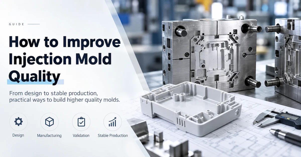
How to Improve Injection Mold Quality From the Beginning
If you want to know how to improve injection mold quality, the first mistake to avoid is treating quality as something that can be inspected into the tool after machining is finished.
A high-quality injection mold is not simply a mold with polished steel, tight machining tolerances, or an expensive mold base. For an OEM buyer, the real measure of mold quality is whether the tool can repeatedly produce acceptable parts under defined production conditions while remaining stable, maintainable, and economically practical over the intended program life.
That means mold quality is created long before final inspection.
It begins with:
Product Requirements → DFM → Tooling Specification → Mold Design → Machining → Fitting → Trial Validation → Stable Process → Quality Control → Preventive Maintenance
Weakness at any one of these stages can appear later as:
- Flash
- Sink marks
- Short shots
- Warpage
- Weld lines
- Dimensional drift
- Difficult ejection
- Excessive cycle time
- Premature tool wear
- Unstable cavities
- Repeated mold repair
DX Molding's current technical-support workflow follows this broader model, covering DFM, mold-flow-related analysis, mold design, machining, T0/T1/T2 trials, dimensional inspection, production support, CPK-related critical-dimension control, AQL inspection, maintenance, and mold modification. DX Molding
Review DX Molding engineering and quality support
The important principle for buyers is simple:
Do not ask only whether a mold is “high quality.” Define what quality must mean for your actual product and production program.
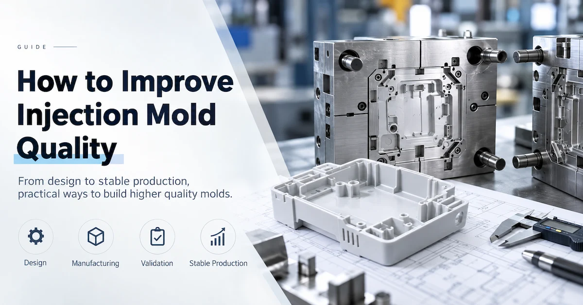
What Does “Injection Mold Quality” Actually Mean?
Before improving quality, the buyer and mold maker need a common definition.
A mold can look excellent on the bench but perform poorly in production. Conversely, a tool may not have unnecessary cosmetic finishing on every hidden component but can still be a strong production mold if its critical systems are correctly engineered.
For most OEM projects, mold quality should be evaluated across six dimensions.
1. Part Quality
Can the mold repeatedly produce parts that meet:
- Critical dimensions
- Assembly requirements
- Cosmetic standards
- Functional requirements
- Surface specifications
- Approved material conditions
2. Tooling Stability
Does the mold operate consistently without frequent:
- Flash development
- Misalignment
- Slide sticking
- Broken ejectors
- Insert movement
- Unplanned repair
3. Process Stability
Can acceptable parts be produced within a practical process window rather than at one fragile combination of machine settings?
4. Maintainability
Can wear components be inspected, serviced, replaced, and restored without excessive downtime?
5. Production Efficiency
Does the mold support realistic:
- Cycle time
- Cooling performance
- Ejection
- Automation
- Scrap control
- Cavity balance
6. Traceability
Can the buyer connect:
Drawing Revision → Mold Revision → Trial Result → Modification → Approved Sample → Production Status
A professional quality system should address all six.
Why Injection Mold Quality Problems Often Start Before the Mold Is Built
Many tooling problems that appear during T0 or mass production originate in decisions made before mold machining.
Consider four examples.
A thick boss behind a cosmetic wall may later create a sink mark.
A long, thin flow path may create filling instability.
An undercut that was not properly reviewed may force an unnecessarily complicated slide.
A critical assembly dimension may be difficult to correct if the tooling engineer was not told that it was critical.
These are not primarily inspection failures.
They are requirement and engineering failures.
This is why one of the highest-leverage ways to improve injection mold quality is to prevent weak product and tooling decisions from moving into steel.
DX Molding's manufacturing workflow currently places DFM and manufacturing-risk assessment before mold design, machining, trial molding, and production. DX Molding
Step 1: Define Quality Before You Ask for a Mold Quote
A supplier cannot engineer the correct quality level from a STEP file alone.
Before tooling starts, the buyer should identify which requirements actually determine whether the part is acceptable.
Build a CTQ List
CTQ means Critical to Quality.
Depending on the component, CTQs might include:
- Mounting-hole position
- Sealing diameter
- Connector location
- Snap engagement
- Flatness
- Assembly gap
- Cosmetic surface
- Wall deformation
- Functional movement
- Leak performance
Not every dimension on a drawing deserves the same engineering priority.
If a drawing contains 150 dimensions but only eight directly affect assembly or function, those eight should receive special attention during:
- DFM
- Mold design
- Steel-safe planning
- Machining
- Trial inspection
- Production control
Separate Three Types of Requirements
A useful project specification separates:
Functional requirements
What the product must do.
Dimensional requirements
What geometry must be controlled.
Cosmetic requirements
What the customer can see or feel.
This prevents teams from treating every issue as a dimensional problem.
Define Acceptance Before Trial
Do not wait until T0 samples arrive to decide whether a part is acceptable.
Agree early on:
- Drawing revision
- Resin
- Critical dimensions
- Measurement methods
- Surface requirements
- Assembly checks
- Functional tests
- Cosmetic limits
Better requirements create better mold decisions.
Step 2: Improve Product DFM Before Improving the Tool
Many “mold quality” problems are actually product-design problems transferred into the mold.
DFM should identify these risks while they are still inexpensive to change.
Review Draft Angle
Insufficient draft can create:
- High release force
- Drag marks
- Scuffing
- Stress whitening
- Difficult ejection
- Tool wear
Draft requirements should also consider texture and surface finish.
Review Wall Thickness
Uneven wall thickness can contribute to:
- Sink marks
- Differential shrinkage
- Long cooling time
- Warpage
- Internal stress
The objective is not always perfectly uniform wall thickness, because functional products often require different structures.
The objective is to identify transitions that create unnecessary molding risk.
Review Ribs and Bosses
Ribs and bosses support:
- Stiffness
- Screws
- PCB mounting
- Alignment
- Assembly
But poorly proportioned features can create sink marks, distortion, or difficult filling.
DFM should evaluate these internal features against external cosmetic surfaces.
Review Undercuts
Each undercut can affect:
- Slide design
- Lifter design
- Tool size
- Cost
- Wear
- Maintenance
The first engineering question should be:
Does the product truly need this undercut?
If yes, engineer the mechanism correctly.
If not, simplifying the part may improve both mold quality and long-term reliability.
DX Molding's support scope explicitly includes draft, wall thickness, fillet, undercut, side-core feasibility, assembly interference, sink, and warpage review. DX Molding
For projects where product design is still changing, DX Molding's custom manufacturing services describe how engineering review is integrated before tooling.
Step 3: Match Mold Specification to the Real Production Program
One common quality mistake is over-specifying unimportant features while under-specifying the areas that determine production life.
The tooling specification should reflect:
- Resin
- Fillers
- Part size
- Annual volume
- Program life
- Cosmetic requirements
- Required cycle time
- Production location
- Maintenance capability
Do Not Select Mold Steel by Name Alone
P20, NAK80, S136, 718H, H13, and other materials can all be appropriate in different situations.
A familiar or expensive steel does not automatically produce a better mold.
Steel selection should consider:
- Wear
- Corrosion
- Polishability
- Heat treatment
- Machining
- Production volume
- Resin abrasiveness
DX Molding's current design support lists project-based steel and mold-life planning rather than presenting one grade as universally superior. DX Molding
Decide Which Components Should Be Replaceable
High-wear areas may benefit from replaceable:
- Inserts
- Gate components
- Slide wear plates
- Ejector components
- Shut-off components
A mold can sometimes become more maintainable by designing expected wear into replaceable components instead of treating every wear surface as permanent.
Define Standard Components
For export tooling, buyers should also consider whether components can be sourced at the destination factory.
A tool that uses difficult-to-source components can create unnecessary downtime later.
Step 4: Improve Mold Design Before Increasing Machining Accuracy
Precision machining cannot correct a weak mold concept.
Before machining begins, review how the mold will:
- Fill
- Pack
- Cool
- Vent
- Open
- Eject
- Move
- Wear
A strong mold design makes machining accuracy useful.
Gate and Runner Design
Gate design influences:
- Filling direction
- Pressure
- Weld lines
- Air traps
- Packing
- Gate vestige
- Appearance
- Warpage
A visually hidden gate is not always the best gate.
If the hidden location creates poor filling, excessive pressure, or uncontrolled weld lines, cosmetic preference may create a larger production-quality problem.
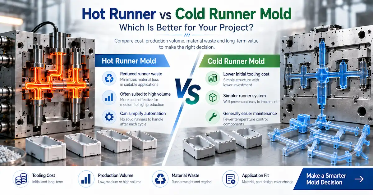
Review Runner Strategy
The correct choice may involve:
- Cold runner
- Hot runner
- Multi-gate system
- Balanced runner
- Valve gate
The choice should match volume, resin, cavity count, appearance, maintenance, and total production economics.
Venting
Poor venting can contribute to:
- Short shots
- Burn marks
- Incomplete filling
- Excessive pressure
- Surface defects
Venting should be treated as a functional part of mold design.
It should not be left until repeated trial problems force local corrections.
Parting-Line Design
The parting line influences:
- Flash
- Cosmetic appearance
- Shut-off reliability
- Tool wear
- Assembly interfaces
For visible products, parting-line approval should happen before tooling is frozen.
Step 5: Treat Cooling as a Quality System, Not Only a Cycle-Time Tool
Cooling is one of the most important elements of mold quality.
Poor cooling may cause:
- Uneven shrinkage
- Warpage
- Dimensional drift
- Long cycle time
- Local hot spots
- Unstable appearance
A mold can fill correctly and still produce inconsistent parts because heat is removed unevenly.
Review Cooling Around High-Risk Features
Pay attention to areas around:
- Thick sections
- Deep cores
- Boss clusters
- Large ribs
- Slides
- Inserts
- Large flat surfaces
Quality and Cycle Time Are Connected
Trying to shorten cycle time without understanding cooling can create unstable production.
A short cycle is only useful if the parts remain acceptable.
For high-volume programs, DX Molding's existing high-volume guide also emphasizes cooling, cavity behavior, repeat production, and maintenance rather than treating cycle time as an isolated target. DX Molding
Review the high-volume tooling guide
Step 6: Improve Ejection, Slides, Lifters, and Moving Components
Many molds lose quality gradually because moving components are not sufficiently robust.
Ejection Problems Can Damage Good Parts
Poor ejection may create:
- Distortion
- Ejector marks
- Whitening
- Drag
- Cracks
- Sticking
Ejection should distribute force appropriately and avoid critical cosmetic or functional areas where possible.
Slides and Lifters Need Long-Term Thinking
Slides and lifters introduce:
- Movement
- Friction
- Alignment
- Wear
- Lubrication
- Maintenance
A complex mold may work during T0 but become unstable later if the mechanism has inadequate support or wear management.
Check Interference Before Machining
3D mold assembly review should confirm that:
- Slides clear adjacent components
- Lifters move safely
- Ejectors do not interfere
- Cooling lines avoid mechanisms
- Mold opening sequence is correct
DX Molding's mold-design support includes cavity-layout review, parting, ejection-system design, cooling layout, 3D assembly, drawings, and spare-parts information. DX Molding
For deeper mold-design review, see the Injection Mold Design Company guide.
Step 7: Control Machining Around Functional Datums
Machining accuracy matters, but buyers should distinguish between accuracy everywhere and accuracy where it affects mold performance.
Critical areas can include:
- Core/cavity alignment
- Shut-offs
- Insert interfaces
- Slide positioning
- Guide systems
- Sealing surfaces
- Gate components
- Critical cavity geometry
CNC Machining
CNC commonly creates:
- Cores
- Cavities
- Inserts
- Mold plates
- Structural components
EDM
EDM is often used for:
- Deep geometry
- Sharp internal features
- Detailed cavities
- Difficult-to-machine regions
Grinding and Finishing
Grinding and fitting can become important for:
- Flatness
- Precision interfaces
- Shut-offs
- Sliding components
DX Molding publicly lists CNC, EDM, fitting, polishing, mold assembly, and inspection within its manufacturing support workflow. DX Molding
The important buyer question is not simply:
“What CNC machine do you have?”
A better question is:
“How do you verify the critical mold dimensions and functional interfaces after machining?”
Step 8: Improve Mold Fitting and Assembly Quality
A mold is a system of interacting components.
Individual components can meet their dimensions and the assembled mold can still perform poorly if fitting is weak.
Assembly should verify:
- Core/cavity alignment
- Parting surface contact
- Slide movement
- Lifter movement
- Ejector movement
- Guide system
- Return system
- Cooling connections
- Limit switches where applicable
- Mold opening sequence
Avoid Solving Every Problem With Hand Fitting
Practical mold making requires fitting skill.
But uncontrolled manual correction can reduce traceability.
Important modifications should be documented so both supplier and buyer understand:
- What was changed
- Why it changed
- Which mold revision now exists
Step 9: Use T0, T1, and T2 to Learn—Not Only to Produce Samples
A good mold trial is an engineering experiment.
The goal should not be:
“We made parts.”
The goal should be:
“We learned whether this mold and process can repeatedly make the required parts.”
T0: Functional Learning
T0 may evaluate:
- Mold opening
- Filling
- Ejection
- Major flash
- Short shots
- Weld lines
- Air traps
- Sink
- Warpage
- Major dimensions
T0 often exposes first-order engineering issues.
It should not automatically be expected to deliver perfect production parts.
T1: Verify Corrections
After modification, T1 can focus on:
- Corrected mold behavior
- CTQ dimensions
- Appearance
- Assembly
- Remaining defects
- Process repeatability
T2 and Later Trials
Further trials may be needed when:
- Tooling was modified
- Product geometry changed
- Dimensions remain unstable
- Cosmetic issues remain
- Process settings remain too narrow
DX Molding's current support page lists T0/T1/T2 reports, dimensional results, appearance defects, CMM data, modification tracking, and molding-parameter records. DX Molding
Step 10: Build a Process Window Instead of One “Perfect” Setting
One of the clearest signs of weak tooling is a mold that only produces acceptable parts at one extremely narrow machine setting.
Good production quality should not depend on constant operator adjustment.
Record the Important Process Variables
Depending on the project, these can include:
- Melt temperature
- Mold temperature
- Injection speed
- Injection pressure
- Packing
- Cooling time
- Cycle time
Distinguish Tool Problems From Process Problems
This matters because the wrong correction can make the mold worse.
For example:
If flash is caused by excessive pressure, cutting the tool may not be the correct first action.
If flash is caused by poor shut-off fitting, reducing pressure may hide the problem but create filling defects.
Quality improvement requires root-cause separation.
Do Not Optimize Cycle Time Too Early
First establish:
Stable Quality → Repeatability → Then Cycle Optimization
Optimizing cycle time before the mold and product are stable can create misleading results.
Step 11: Improve Measurement Before Tightening Tolerances
Inspection data is only useful when the measurement method is stable.
A dimension can change depending on:
- Part temperature
- Time after molding
- Moisture conditioning
- Fixture
- Datum selection
- Measurement force
- Instrument
- Free-state deformation
For critical characteristics, define how the dimension will be measured.
DX Molding's current site identifies CMM inspection, first-article validation, critical-dimension control, and CPK-related capability support within its project workflow. DX Molding
CMM Does Not Automatically Mean Better Quality
A CMM is a measurement tool.
Quality still depends on:
- Correct datum
- Correct fixture
- Correct drawing interpretation
- Stable molded condition
- Correct probing strategy
Inspect by Cavity
For multi-cavity molds, do not combine all data without cavity identification.
Cavity 1 and Cavity 8 may behave differently because of:
- Filling balance
- Cooling
- local dimensions
- venting
- wear
Quality improvement becomes much faster when the team knows which cavity produced which result.
Step 12: Use Root-Cause Analysis Instead of Repeated Mold Modification
Repeated modifications without clear diagnosis can make mold quality worse.
Before changing steel, separate possible root causes into four groups:
Product Design
Geometry, wall thickness, ribs, bosses, material requirement.
Mold Design / Tooling
Gate, venting, cooling, fitting, dimensions, ejection.
Process
Temperature, speed, pressure, packing, cooling.
Material / Measurement
Resin condition, shrinkage, moisture, measurement method.
The table below gives a practical starting point.
| Quality Problem | Possible Product Cause | Possible Tool Cause | Possible Process Cause | Improvement Direction |
|---|---|---|---|---|
| Flash | Thin/weak geometry | Shut-off or fitting issue | Excessive pressure | Check tool fit before masking with settings |
| Sink marks | Thick ribs/bosses | Gate/cooling layout | Insufficient packing | Review geometry + packing + cooling |
| Short shot | Long/thin flow path | Venting or gate restriction | Low temperature/pressure | Identify flow restriction first |
| Warpage | Uneven wall thickness | Uneven cooling | Packing/cooling imbalance | Compare geometry, cooling and process |
| Weld line | Multiple flow fronts | Gate location | Temperature/speed | Review gate strategy and process |
| Burn mark | Difficult air evacuation | Poor venting | Excessive speed | Improve venting and process balance |
| Sticking | Low draft | Surface/ejection issue | Insufficient cooling | Review release geometry and ejection |
| Dimensional drift | Sensitive geometry | Cooling/tool dimension | Process instability | Separate mold dimension from process variation |
| Surface drag | Draft/texture conflict | Polish/release issue | Ejection timing | Correct release system |
| Cavity imbalance | Part sensitivity | Runner/gate imbalance | Process amplifies imbalance | Measure by cavity before adjustment |
This is one of the most important principles in how to improve injection mold quality:
Do not modify the mold until the team understands whether the mold is actually the root cause.
How to Improve Mold Quality During Mass Production
Tool approval is not the end of quality management.
Production gradually changes the tooling system.
Components wear.
Lubrication changes.
Resin deposits can accumulate.
Cooling circuits can become less efficient.
Ejectors can wear.
Shut-offs can lose condition.
Establish Preventive Maintenance
Maintenance planning may include:
- Cleaning
- Lubrication
- Anti-rust protection
- Cooling inspection
- Ejector inspection
- Slide inspection
- Gate inspection
- Wear-component checks
- Spare-parts replacement
DX Molding's support information includes mold cleaning, anti-rust treatment, lubrication, wearing-spare-parts planning, overhaul, refurbishment, and troubleshooting for issues such as flash, broken ejector pins, and sticking. DX Molding
Track Quality Drift
Do not wait until the mold fails completely.
Monitor indicators such as:
- Flash increasing
- Part dimensions drifting
- Cycle time increasing
- Ejection becoming unstable
- More operator adjustment
- Increasing cosmetic defects
Gradual drift often provides warning before major downtime.
How to Improve Injection Mold Quality for High-Volume Production
High-volume tools require a stronger focus on repeatability and maintenance.
Important priorities include:
- Cavity balance
- Cooling consistency
- Wear components
- Robust ejection
- Stable gates
- Replaceable inserts
- Maintenance access
- Cavity traceability
Validate Every Cavity
A multi-cavity mold should not be approved because one sample looks correct.
Check each active cavity against:
- CTQ dimensions
- Appearance
- Part weight where useful
- Assembly
- Process stability
Design Maintenance Into the Tool
For long programs, ask:
- Which components will wear?
- Which are replaceable?
- Which spares should be stored?
- How difficult is disassembly?
- Can critical areas be serviced without major tool rebuilding?
Quality is easier to maintain when maintenance was considered during mold design.
How to Improve Quality for Precision Plastic Parts
Precision projects require more than writing tighter tolerances.
The buyer should define:
- Which dimensions are genuinely critical
- Datums
- Measurement method
- Conditioning
- Assembly relationship
- Capability requirement
- Cavity identification
Unnecessarily tight tolerances can:
- Increase machining cost
- Increase trial time
- Reduce process window
- Create unnecessary rework
Precision should be applied where the product needs it.
Not everywhere.
How to Improve Quality for Cosmetic Parts
For customer-visible parts, define appearance before the first trial.
Consider:
- Texture
- Gloss
- Parting line
- Gate vestige
- Weld lines
- Flow marks
- Sink marks
- Ejector marks
- Scratch limits
- Color
Separate Cosmetic Approval From Dimensional Approval
A part may be dimensionally correct and cosmetically unacceptable.
Or visually attractive and dimensionally unsuitable for assembly.
Use separate acceptance criteria.
How to Improve Quality When the Mold Will Be Transferred to Another Factory
An export mold can produce excellent samples at the mold maker's factory and still create problems after transfer.
The reason may not be poor workmanship.
The destination plant may use different:
- Injection machine
- Controller
- Cooling
- Resin handling
- Process parameters
- Maintenance practices
Before transfer, define:
- Mold dimensions
- Machine compatibility
- Clamping
- Cooling connections
- Electrical interfaces
- Hot runner controller
- Lifting points
- Spare parts
- Trial parameters
- Documentation
Quality transfer is easier when the receiving factory understands the validated production conditions.
Build a Mold Quality Gate System
A practical quality-improvement program should prevent defects from moving to the next stage.
| Quality Gate | Main Question | Evidence |
|---|---|---|
| Gate 1: Product Release | Is the product ready for tooling? | Controlled CAD, CTQs, DFM approval |
| Gate 2: Mold Design | Can the tool produce and maintain the part? | Mold review, material/spec approval |
| Gate 3: Manufacturing | Were critical components made correctly? | Inspection and fitting records |
| Gate 4: Trial | Does the tool operate and make acceptable parts? | T0/T1/T2 reports |
| Gate 5: Validation | Are CTQs, appearance and assembly acceptable? | CMM/inspection/assembly results |
| Gate 6: Production | Is quality repeatable under stable conditions? | Process and quality records |
| Gate 7: Lifecycle | Can quality be maintained over time? | Maintenance and modification history |
This is more effective than relying on a single “final mold inspection.”
How Should Buyers Audit Injection Mold Quality?
A buyer does not need to inspect every machining operation personally.
But the supplier should be able to explain its control logic.
Ask how the factory manages:
Product and Engineering Control
- Drawing revisions
- DFM
- CTQs
- Engineering changes
Tooling Specification
- Steel
- Components
- Cavity count
- Mold life
- Runner
- Surface
Manufacturing
- CNC
- EDM
- Inspection
- Fitting
- Assembly
Validation
- T0/T1/T2
- Inspection reports
- CMM
- Defect records
- Modification tracking
Production
- Process parameters
- Critical dimensions
- First article
- In-process checks
Lifecycle Support
- Maintenance
- Spare parts
- Modification
- Repair
DX Molding's current site documents a quality flow that includes incoming-material inspection, mold inspection, first article, in-process QC, final inspection, packaging inspection, and quality documentation. DX Molding
For broader supplier qualification, review the Injection Mold Supplier Evaluation Checklist.
What Quality Records Should Buyers Request?
The exact documentation depends on the project.
Useful records can include:
- Approved DFM
- Controlled CAD revision
- Mold design revision
- Tool-steel specification
- Mold BOM
- Trial report
- Defect list
- Modification record
- Dimensional report
- CMM data
- Process parameters
- Approved sample reference
- Spare-parts list
- Maintenance instructions
The purpose is not paperwork for its own sake.
Documentation allows the buyer and supplier to understand what was approved.
Why a Good-Looking T0 Sample Can Still Hide a Poor Mold
One of the biggest sourcing traps is approving a tool based on several attractive samples.
A small sample batch may not reveal:
- Thermal imbalance
- Progressive flash
- Cavity imbalance
- Component wear
- Ejection instability
- Narrow process window
- Long-term warpage
- Maintenance difficulty
This is why injection mold quality should be evaluated as a production system, not only a sample.
A stronger question is:
Can this mold repeatedly produce acceptable parts without excessive adjustment, repair, scrap, or downtime?
How to Compare Mold Quality Without Choosing the Most Expensive Tool
Higher price does not automatically mean higher quality.
The goal is specification alignment.
A low-volume tool and a million-part production tool should not necessarily use the same:
- Steel
- Cavity strategy
- Components
- Maintenance design
- Hot runner
- Validation plan
Compare Supplier Quotations on the Same Basis
Normalize:
- Steel
- Cavity count
- Runner system
- Mold base
- Standard components
- Mold life
- Trial scope
- Inspection
- Spare parts
- Documentation
- Modification terms
If two quotations have very different prices, determine whether they actually describe the same mold.
Injection Mold Quality Improvement Priority Matrix
Different projects should prioritize different quality controls.
| Project Type | Highest Priorities |
|---|---|
| Low-volume product | DFM, reasonable tooling cost, flexible modification |
| High-volume production | Cooling, wear, cavity balance, maintenance |
| Precision component | CTQs, measurement, tooling stability |
| Cosmetic enclosure | Gate, parting, surface, sink, ejection |
| Automotive part | Repeatability, documentation, maintenance, assembly |
| Electronics housing | Warpage, clips, bosses, connector alignment |
| Export mold | Machine compatibility, documentation, spare parts |
| Multi-cavity mold | Cavity balance, cavity identification, cooling |
There is no universal “best mold quality specification.”
Quality should match the production objective.
What Should Be Included in an RFQ to Improve Mold Quality?
One of the easiest ways buyers can improve tooling results is to improve the RFQ.
Send:
- Current 3D CAD
- Controlled 2D drawing
- Exact or candidate resin
- Critical dimensions
- Assembly information
- Cosmetic requirements
- Annual volume
- Program duration
- Mold-life expectation
- Production location
- Target machine where relevant
- Required reports
- Trial expectations
- Open engineering questions
DX Molding's service page specifically asks customers to provide drawings, samples, materials, target quantity, finish, color, tolerance, and application information so feasibility and tooling requirements can be reviewed before production. DX Molding
How DX Molding Supports Injection Mold Quality Improvement
DX Molding's current project workflow combines engineering, tooling, trial, quality inspection, production support, and lifecycle support rather than limiting quality to final mold inspection.
Published capabilities include:
- DFM
- Material review
- Mold flow analysis
- Cavity-layout planning
- Cooling optimization
- Ejection design
- CNC
- EDM
- Mold fitting
- T0/T1/T2 trials
- CMM inspection
- Critical-dimension control
- CPK-related analysis
- AQL inspection
- Process tuning
- Mold maintenance
- Mold modification DX Molding
Buyers can also review DX Molding's custom plastic injection mold manufacturing capabilities and plastic injection molding production services when evaluating whether tooling and production should remain with the same supplier.
Injection Mold Quality Improvement Checklist
Before final mold approval, confirm that the project can answer all of the following:
- Is the approved product revision clearly identified?
- Are CTQ dimensions defined?
- Has DFM been completed?
- Are wall thickness, draft, ribs, bosses, and undercuts reviewed?
- Is the mold steel appropriate for the program?
- Are gates, runners, venting, cooling, and ejection reviewed?
- Are slides and lifters designed for maintainability?
- Are critical mold components inspected after machining?
- Is mold fitting documented?
- Are T0/T1/T2 findings traceable?
- Are inspection methods defined?
- Are samples identified by cavity where required?
- Is there a stable molding process window?
- Are cosmetic and dimensional approval separated?
- Is preventive maintenance planned?
- Are spare parts defined?
- Are engineering changes controlled?
- Are transfer requirements defined if the mold moves?
- Are production quality records available?
- Is final approval based on repeatability rather than one good sample?
If several answers are unclear, the project may not yet be ready for final acceptance.
Frequently Asked Questions
How Can I Improve Injection Mold Quality Before Tooling Starts?
Start by defining CTQs, material, appearance, assembly, production volume, and acceptance requirements. Complete DFM before steel cutting and resolve product risks such as insufficient draft, uneven walls, unnecessary undercuts, sink-risk features, and difficult assembly interfaces.
What Is the Most Important Factor in Injection Mold Quality?
There is no single factor. Good mold quality comes from alignment between product design, mold design, tooling specification, machining, fitting, trial validation, process control, inspection, and maintenance.
Does Better Mold Steel Always Improve Mold Quality?
No. Steel should match resin, production volume, wear, corrosion, finish, maintenance, and budget. An expensive steel cannot compensate for poor gate design, weak cooling, bad fitting, or unstable processing.
Can CNC Machining Accuracy Guarantee a High-Quality Mold?
No. CNC accuracy is important, but mold quality also depends on engineering, EDM, fitting, assembly, cooling, venting, ejection, trials, and process stability.
Why Does a Mold Produce Good T0 Samples but Poor Mass-Production Parts?
Possible causes include thermal imbalance, a narrow process window, cavity imbalance, wear, inconsistent material, unstable processing, or insufficient validation. T0 proves only an early tooling condition; it does not automatically prove long-term production capability.
How Do I Reduce Flash in an Injection Mold?
First identify whether flash is caused by product design, mold fitting, shut-off condition, tooling wear, or excessive processing pressure. Do not change steel until the root cause is understood.
How Do I Reduce Warpage?
Review wall thickness, shrinkage behavior, gate position, cooling balance, packing, ejection, and material characteristics together. Warpage is often caused by interacting design, tooling, and process factors rather than one setting.
How Should Multi-Cavity Mold Quality Be Controlled?
Identify every cavity and evaluate critical dimensions, appearance, filling, cooling, and assembly by cavity. Do not approve the entire tool based on the best-performing cavity.
How Often Should an Injection Mold Be Maintained?
There is no universal interval. Maintenance frequency depends on resin, fillers, tool design, operating environment, production volume, moving mechanisms, and observed wear. Establish preventive checks based on the actual tooling program.
What Should I Send DX Molding for a Mold Quality Review?
Prepare your current CAD, 2D drawing, resin, annual volume, critical tolerances, cosmetic requirements, assembly information, existing defect data, mold destination, and production expectations. For project-specific engineering support, use the DX Molding contact page.
Conclusion
Understanding how to improve injection mold quality starts with preventing weak decisions from reaching production. Focus on clear CTQs, DFM, robust mold design, controlled machining and fitting, structured trials, reliable measurement, stable processing, and preventive maintenance rather than relying on final inspection alone.
For a tooling-quality or production-risk review, prepare your CAD, material, critical dimensions, annual volume, existing defects, and validation requirements, then contact DX Molding for a project evaluation.