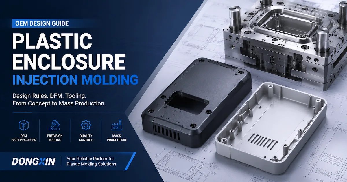
Plastic enclosure injection molding is successful when the housing is designed as a complete electronic assembly, not as an isolated shell. The mold, resin, wall structure, PCB location, connector openings, fastening method, cosmetic surfaces, sealing strategy, and inspection plan must agree before production steel is cut.
For an electronics OEM, the practical question is not only whether a CAD shape can be filled. The useful question is whether the proposed enclosure can be molded repeatedly, assembled without forcing the PCB or connectors, pass its appearance and dimensional checks, and remain serviceable at the target production volume. This guide explains the design decisions that usually determine that result and gives buyers a specification checklist for comparing suppliers.
DX Molding's public product information describes custom plastic injection molding for electronic device housings and connectors, with OEM/ODM support, mold development, secondary processing, assembly, and mass-production support. Those public capabilities should still be confirmed for the specific enclosure, resin grade, tolerance, volume, inspection method, and delivery plan in the quotation.
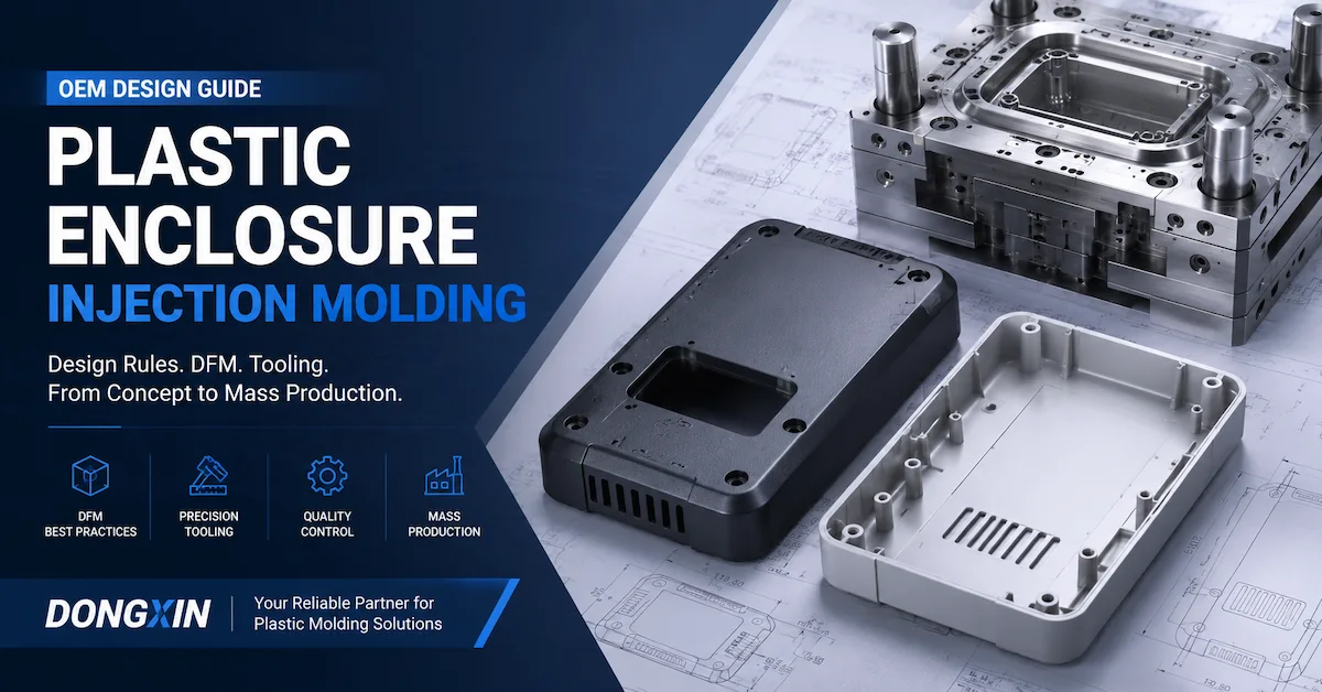
Have an electronics housing under development? Send the latest CAD, 2D drawing, PCB outline, connector locations, resin requirement, annual quantity, surface finish, and assembly concerns for a manufacturing review.
Review Plastic Enclosure ManufacturingWhat Is Plastic Enclosure Injection Molding?
Plastic enclosure injection molding, also called Plastic enclosure molding when the process is discussed as a broader production route, is the process of producing an electronic housing by injecting molten thermoplastic into a custom mold shaped around the product's internal components, assembly interfaces, cosmetic requirements, and expected production quantity. A housing may include two mating shells, a cover, a base, a bezel, a battery door, a sensor cover, or a structural internal frame.
An injection molded electronics housing may integrate:
- PCB locating posts and mounting bosses.
- Screw towers, threaded inserts, or self-tapping screw features.
- Snap fits, hooks, latches, and service-release features.
- Connector openings, cable exits, strain-relief features, and button windows.
- Display openings, light-pipe seats, speaker grilles, and ventilation slots.
- Gasket grooves, sealing lands, overlap joints, and water-shedding geometry.
- Internal ribs, brackets, shields, and component supports.
The housing therefore has several simultaneous jobs: protect the electronics, locate the components, transfer assembly loads, present an acceptable exterior, and survive the intended environment. A design that is easy to mold but causes connector misalignment is not a successful enclosure. A design that looks good but traps the PCB during assembly is not production-ready.
Start With the Electronics and Assembly, Not the Mold
The first design review should map the enclosure to the actual electronic assembly. Before plastic enclosure mold design begins, the buyer and supplier should agree which features are functional, which are cosmetic, and which can move if the mold requires a change.
PCB and component envelope
Provide the PCB outline, keep-out areas, component height map, mounting-hole pattern, connector envelope, cable bend requirements, battery position, and any heat-generating components. A housing wall can be dimensionally correct while still interfering with a tall capacitor, shield, antenna, cable, or connector latch. The CAD review should include the installed assembly rather than only the empty housing.
For each locating feature, define its purpose. A post may locate the PCB laterally, support it vertically, prevent rotation, or carry a screw clamp load. These functions need different clearances and support geometry. If every post is treated as a tight locator, assembly variation can accumulate and force the board into a distorted position.
Connector and user-interface alignment
Connector openings, buttons, displays, LEDs, microphones, and switches are frequent causes of late enclosure changes. The drawing should identify the datum scheme used to control them. A connector opening may need clearance for the mating plug, but excessive clearance can create a visible gap or expose the internal seal. A button opening may need a controlled radial gap while also allowing the button to travel without rubbing.
Ask the supplier to check these features in the assembled condition:
- Connector centerline to PCB datum.
- Connector opening size and edge clearance.
- Button travel, return, and side-wall clearance.
- Display or lens opening alignment.
- LED light leakage paths and internal barriers.
- Cable exit direction and bend radius.
Serviceability, sealing, and assembly sequence
A housing assembled with screws, snaps, adhesive, heat staking, ultrasonic welding, or an overmold needs a different part design. The assembly sequence should be described before tooling because it determines whether a feature is accessible, whether a snap can be released, and whether a gasket can be installed without twisting.
For a gasketed enclosure, define the sealing land, compression direction, joint gap, corner radii, screw sequence, and inspection method. Do not assume that a nominal gasket groove guarantees sealing. The molded part may need controlled flatness, local support, and a stable clamping path. The supplier should identify which surfaces are sealing CTQs and which are general surfaces.
Need mold and part development together? A practical enclosure review should connect product structure, custom mold design, trial molding, inspection, and production rather than treating the mold as a separate purchase.
View Custom Molding ServicesPlastic Enclosure Material Selection for Electronics
Plastic enclosure material selection should start with the application environment and failure modes, not with a generic request for the cheapest resin. The selected grade affects filling, shrinkage, impact performance, heat resistance, surface appearance, chemical resistance, flammability requirements, color stability, and mold-processing conditions.
DX Molding's public plastic molding page lists ABS, PP, PE, PVC, Nylon, PC, and custom engineering plastics among its material options. The actual grade, filler, color concentrate, flame-retardant package, and certification requirement must be confirmed for the enclosure project. Generic names such as PC or Nylon are not sufficient for a production specification.
| Material family | Why buyers consider it | Questions before approval |
|---|---|---|
| ABS | Often considered for appearance, impact, processability, and consumer housings. | What surface finish, impact level, temperature, and regulatory requirement apply? |
| PC | Often considered when impact or heat performance is important. | Is the grade compatible with the required finish, chemical exposure, color, and stress level? |
| PC/ABS or engineering blend | May be considered when appearance and performance need to be balanced. | Which supplier grade, shrinkage data, flame rating, and approved substitute rules apply? |
| PP or PE | May suit chemical resistance, living features, or lighter flexible designs. | Can the enclosure meet stiffness, creep, sealing, and dimensional requirements? |
| Nylon or other engineering plastic | May be relevant for functional brackets, mounts, or demanding mechanical loads. | How will moisture, filler orientation, shrinkage, and surface appearance affect the housing? |
Material questions that change the mold design
A filled resin can create directional shrinkage and visible flow or fiber effects. A flame-retardant grade may process differently from an unmodified grade. A transparent or high-gloss housing has different gate and weld-line requirements from a textured industrial cover. A material change after the mold is designed can affect gate size, cooling assumptions, ejection, dimensional compensation, and trial conditions.
Before quotation, record the resin manufacturer and grade if known, color, filler percentage, flame rating, recycled-content requirement, food or medical contact requirement if applicable, and approved alternates. If the grade is not fixed, ask the supplier to quote the assumption and state what must be rechecked when the grade is selected.
Plastic Enclosure DFM: Design Problems That Need Specific Decisions
Wall thickness and local mass
Reasonably uniform wall thickness helps make filling, cooling, shrinkage, and dimensional behavior more predictable. The risk is not simply a wall that is globally too thick. It is a local change in section around a boss, rib intersection, corner, connector support, battery pocket, or mounting post. These zones can remain hotter and shrink differently from the surrounding shell.
The correct wall value depends on resin, flow length, part size, stiffness, appearance, and production requirements. Do not place a universal wall number in the drawing without checking the selected grade and geometry. Instead, identify the nominal wall, the allowed transitions, and the locations where a thick feature may print through on a visible surface.
Ribs, bosses, and mounting posts
Ribs can improve stiffness without adding material to the entire wall, but a rib that is too thick or too close to the outside skin can create sink. Bosses should be designed around the fastener, load, insertion method, and surrounding wall. A hollow boss supported by gussets is often easier to control than a solid cylinder, but the final design must be checked for screw pull-out, cracking, tool access, draft, and ejection.
For every critical boss, define:
- Fastener type, size, insertion direction, and installation torque if known.
- Required hole diameter and depth, including any insert or self-tapping condition.
- Boss height, support ribs, base radius, and clearance from cosmetic walls.
- PCB or component alignment function.
- Inspection method and assembly test.
Draft, texture, and ejection
Draft is a release requirement, not only a cosmetic preference. Outer walls, inner walls, ribs, bosses, deep pockets, connector openings, and textured surfaces should be reviewed in the actual pull direction. Texture can increase drag, so a surface specification should identify the finish and the faces that require additional release allowance.
Ask the supplier to show the proposed ejection locations. Ejector marks should not appear on customer-visible surfaces, sealing lands, lettering, or thin unsupported panels unless the drawing accepts them. A housing can pass a dimensional check and still fail cosmetic approval if the ejection pattern leaves visible rings or whitening.
Undercuts, latches, and service access
Snap hooks, side openings, cable channels, grille geometry, and latch returns can create undercuts. The preferred solution may be a slider, lifter, insert, parting-line change, flexible shutoff, or a redesign of the feature. Each choice changes tooling cost, maintenance, mold movement, and the risk of flash.
Before approving a snap-fit, check the assembly direction, required deflection, material strain, repeated service cycles, access for release, and whether the snap is supported by a wall or rib. A snap that is easy to mold but impossible to disengage for service can create a field-repair problem.
Plastic Enclosure Mold Design for Appearance and Function
Parting line and visible surfaces
The parting line should be selected with appearance, sealing, assembly, draft, and tool construction in mind. On a two-piece electronics housing, the split line often affects the panel gap, gasket path, connector openings, and the way the upper and lower shells register. It should not be placed on a primary cosmetic face just because it makes the mold easier to build. Review the proposed structure together with the plastic injection mold tooling scope so product and tool decisions remain connected.
Mark the following surfaces on the drawing:
- Customer-visible Class A or appearance-critical faces.
- Sealing lands and gasket grooves.
- Connector, display, button, and cable openings.
- Mating faces and screw-clamp areas.
- Acceptable gate, weld-line, ejector, and parting-line zones.
Gate position and weld lines
Gate location affects flow length, packing, weld-line position, gate vestige, air evacuation, and warpage. In electronics housing injection molding, these effects can appear around display windows, button openings, logos, connector cutouts, or large flat panels. The best gate is not automatically the one nearest the machine or the easiest to trim.
The DFM review should show the proposed gate location and identify the likely weld-line and air-trap areas. If the weld line must occur near a structural or cosmetic feature, discuss whether the geometry, venting, gate strategy, material, or process should change. The supplier should distinguish a predicted flow risk from a defect actually observed in a trial.
Cooling and flatness
Large flat housing panels can warp when opposite regions cool or shrink differently. Cooling should be considered around broad skins, thick bosses, corners, mounting posts, battery pockets, and insert boundaries. The cooling layout should be reviewed in section views so the buyer can see the relationship between the molded surface, channel, ejector system, and remaining steel.
Cooling cannot compensate for every design problem. A housing with uneven walls, unbalanced packing, high fiber orientation, or an unsuitable gate may still distort after a cooling change. The correct validation method compares the cooling hypothesis with part geometry, material, process parameters, and measured results.
Common Defects in Injection Molded Electronics Housing
Defect investigation should begin with a defined symptom, location, material lot, cavity, process condition, and inspection method. The same visible mark can have more than one cause. For example, a sink mark may result from local mass, insufficient packing, a hot spot, or a combination of them.
| Observed problem | Likely design or process contributors | Useful verification |
|---|---|---|
| Sink near a boss or rib | Local mass, thick rib base, packing loss, or slow cooling behind the cosmetic wall. | Section review, wall-thickness measurement, visual grading, and controlled process comparison. |
| Panel warpage or rocking | Uneven cooling, nonuniform wall, gate or packing imbalance, fiber orientation, or ejection load. | Flatness fixture or datum method, measured map, cavity traceability, and process record. |
| Short shot or incomplete grille | Long flow path, thin section, early freeze, poor venting, or insufficient process window. | Filling observation, vent review, pressure and temperature record, and gate or runner review. |
| Visible weld line | Flow fronts meet near an opening, rib, insert, or feature with inadequate temperature or venting. | Flow-risk map, trial samples, cosmetic limit sample, and functional strength check if relevant. |
| Flash at split or shutoff | Parting-line condition, shutoff wear, clamp or pressure condition, or insufficient support. | Parting-line inspection, flash limit, mold condition record, and repeat samples. |
| Drag, whitening, or ejector marks | Insufficient draft, texture drag, unbalanced ejection, or part still too hot at release. | Ejection review, draft measurement, mark-location map, and controlled ejection observation. |
| Connector or PCB misalignment | Datum stack-up, post location, shell distortion, opening tolerance, or assembly sequence. | CMM or defined dimensional inspection plus actual PCB and connector assembly test. |
| Seal leakage or gasket pinch | Gasket groove variation, housing flatness, joint gap, corner radius, screw sequence, or compression mismatch. | Gasket installation check, closure torque, flatness measurement, and agreed leak test. |
How to Validate an Electronics Housing Before Production Release
Validation should connect the mold, molded part, assembly, and intended use. A CMM report alone does not prove that a housing assembles correctly, that a cosmetic surface is acceptable, or that a gasket seals. The acceptance plan should state which features are measured, which samples are assembled, and what conditions apply.
1. Design and mold review
Before machining, review the controlled CAD revision, 2D drawing, material grade, parting line, gate, cooling, ejection, slides, lifters, inserts, surface finish, and critical-to-quality features. The supplier should identify open risks, assumptions, and the owner of each action. A design review is only useful if it records decisions rather than producing a generic list of molding terms.
2. T0 and T1 sample review
During early trials, record the material, machine, mold temperature, injection and packing conditions, cooling or cycle setting, cavity identity, and sample revision. Check filling, short shots, flash, sink, weld lines, burns, ejection marks, warpage, and visible finish. The first trial is evidence about the actual tool, not proof that every production condition is already stable.
3. Dimensional and assembly verification
Measure the datums, connector openings, PCB posts, screw holes, mating surfaces, sealing lands, panel gaps, and other CTQs using the method specified on the drawing. CMM data may be appropriate for defined points and features, while flatness, profile, appearance, and assembly may require separate fixtures or checks.
Perform an actual assembly check with the intended PCB, connector, fasteners, gasket, buttons, display or other critical components where available. Record whether the assembly requires force, whether screws seat consistently, whether the connector is centered, and whether the shell closes without lifting or stressing the board.
4. Process and repeatability review
Once corrections are complete, confirm that the approved parts come from the intended resin and process window. For multi-cavity tools, keep cavity identity and sample traceability. Check that the enclosure remains within the agreed limits across repeated shots, not only on the best-looking sample selected from a trial.
5. Environmental or functional testing
Where the application requires it, add tests for temperature exposure, chemical contact, impact, vibration, button or latch cycling, connector insertion, screw torque, gasket sealing, or ingress protection. The exact test method and pass criteria must be agreed by the product owner. Do not describe a generic mold trial as environmental qualification.
OEM Plastic Enclosure Manufacturing Workflow
A controlled OEM plastic enclosure manufacturing program should produce a clear output at each stage:
- Project input review: collect 3D CAD, 2D drawings, PCB and connector data, resin, quantity, finish, assembly method, and target market requirements.
- Plastic enclosure DFM: check wall transitions, draft, ribs, bosses, snap fits, undercuts, parting line, gates, cooling, ejection, and tolerance strategy.
- Quotation and scope confirmation: define tooling ownership, mold structure, cavities, steel assumptions, trial scope, inspection, production, assembly, packaging, and delivery responsibilities.
- Plastic enclosure mold design: release the approved mold concept with sections through critical features and a documented risk list.
- Machining and assembly: produce cores, cavities, inserts, slides, lifters, ejector components, and cooling connections, then fit and inspect the mold.
- Trial molding and correction: compare samples to the drawing, appearance standard, assembly check, and process record; assign changes before approval.
- Production and secondary operations: run the approved resin and process, then perform trimming, polishing, assembly, labeling, or packaging when included in scope.
DX Molding's public Services page describes a workflow from requirements and file review through DFM, quotation, mold design, CNC and EDM machining, trial molding, inspection, sample approval, mass production, packaging, and delivery. The page also states that CAD files, 2D drawings, STEP/STL files, samples, material requirements, target quantity, finish, color, and tolerance notes can be submitted for review. These are published service descriptions; the quotation should define exactly what applies to the buyer's enclosure.
Plastic Enclosure Procurement Specifications Checklist
A supplier cannot quote a stable enclosure program from a product name alone. The RFQ should contain enough information to distinguish an appearance housing, a structural electronics enclosure, a sealed device, and a high-volume consumer cover. Use the following checklist to reduce ambiguous offers.
| No. | RFQ item | What to specify | Evidence to request |
|---|---|---|---|
| 1 | Part data | Controlled 3D CAD, 2D drawing, revision, and product envelope. | File list and revision confirmation. |
| 2 | Electronic assembly | PCB, connector, component heights, cables, battery, display, and keep-outs. | Assembly fit review and interface map. |
| 3 | Material | Polymer, grade, color, filler, flame rating, and approved alternates. | Resin data and material assumption record. |
| 4 | Volume and tooling | Annual demand, batch size, target cavities, prototype need, and mold ownership. | Tooling concept and production plan. |
| 5 | Appearance | Visible zones, gloss, texture, color standard, logo, gate and parting-line limits. | Cosmetic standard and approved sample. |
| 6 | Assembly | Screws, snaps, inserts, adhesives, welding, gasket, torque, and service sequence. | Assembly work instruction and fit test. |
| 7 | CTQs and tolerances | Datums, connector alignment, PCB posts, sealing surfaces, gaps, flatness, and critical dimensions. | Inspection plan, CMM or fixture method, and report format. |
| 8 | Mold scope | Cavity count, runner or gate concept, slides, lifters, inserts, cooling, and ejection. | Mold layout and critical section views. |
| 9 | Validation | T0/T1 scope, samples, inspection, assembly, environmental or leak tests. | Trial report and corrective-action list. |
| 10 | Supply and delivery | Production quantity, packaging, labeling, inspection release, and delivery destination. | Quotation scope and shipment plan. |
What to Ask a Custom Plastic Enclosure Manufacturer
When comparing a custom plastic enclosure manufacturer, ask for evidence tied to the actual part rather than a general capability statement. The supplier should explain who owns the product design, who approves the DFM, which revision is being tooled, how changes are controlled, and which results are measured at trial.
Useful supplier questions include:
- Which enclosure features are most likely to affect mold cost or lead time?
- Where will the parting line, gates, ejectors, sliders, and lifters be located?
- Which visible surfaces may show gate, weld-line, ejector, or parting-line evidence?
- How are PCB, connector, gasket, and screw interfaces measured?
- Which material grade and shrinkage assumption are used for the mold design?
- What will be checked at T0 and T1, and how are cavity samples identified?
- Which tooling corrections are included, and how are process changes separated from mold changes?
- Can the same program support molded parts, secondary processing, assembly, packaging, and delivery?
DX Molding's public pages identify Shenzhen DongXin Technology Co., Ltd. as a provider of custom plastic molding, plastic injection molds, OEM/ODM development, industrial design, CNC machining, trial molding, and related production support. The public plastic molding page also states that electronic device housings and connectors are application areas and lists secondary processing, assembly, OEM/ODM customization, and inspection-related benefits. Treat these as published capability descriptions and confirm the exact equipment, material, inspection, minimum order, lead time, packaging, and acceptance terms for the specific RFQ.
When Prototype Enclosures Should Come Before Production Tooling
Production tooling is appropriate when the enclosure geometry, PCB, connector positions, resin, appearance, and assembly method are sufficiently stable. A prototype or soft-tool route may be more useful when the team still needs to confirm hand feel, PCB fit, cable routing, button travel, gasket compression, or service access.
Do not use a prototype to approve production-critical dimensions without checking the process difference. Prototype materials and processes may not reproduce the shrinkage, texture, weld lines, ejection behavior, or assembly stiffness of the final injection molded electronics housing. The prototype should answer clearly defined design questions and feed changes into the controlled production CAD.
Frequently Asked Questions About Plastic Enclosure Injection Molding
What is the best material for an electronics enclosure?
There is no universal best material. ABS, PC, PC/ABS, PP, PE, Nylon, and other engineering plastics may be considered depending on impact, heat, chemicals, appearance, stiffness, flame performance, cost, and regulatory requirements. The approved supplier grade matters more than the generic polymer name. Plastic enclosure material selection should be recorded before final mold and process decisions.
How thick should a plastic electronics enclosure be?
There is no single wall thickness that suits every enclosure. The correct value depends on resin, flow length, part size, stiffness, cosmetic surfaces, ribs, bosses, production conditions, and assembly loads. The design objective is a controllable structure with reasonably uniform walls and planned local transitions, not simply the thickest possible housing.
Why do sink marks appear around enclosure bosses?
A boss or rib intersection can create a local mass that cools and shrinks differently from the surrounding shell. Packing, cooling, wall relationships, and material also contribute. Check the section thickness, boss support strategy, cosmetic wall, process record, and visual limit sample before deciding whether the correction belongs in geometry, tooling, or molding conditions.
How can connector alignment be controlled in molded housing parts?
Define datums around the PCB, connector, and housing mating features, then inspect the opening and mounting posts together with the actual assembly. CMM or dimensional inspection can verify defined features, but an assembly test is still needed to confirm insertion, retention, alignment, and clearance.
What is included in plastic enclosure DFM?
Plastic enclosure DFM should cover wall thickness, ribs, bosses, draft, texture, undercuts, parting line, gates, weld lines, vents, cooling, ejection, inserts, slides, lifters, material, tolerances, cosmetic surfaces, assembly, and inspection. A useful report links each concern to a proposed action and identifies whether the risk affects cost, lead time, appearance, function, or production stability.
Can snap fits be molded into an electronics housing?
Yes, but the snap must be designed around resin flexibility, deflection, stress, assembly direction, release access, and mold movement. An undercut may require a slider, lifter, insert, or a change to the part orientation. Repeated service cycles should be tested when the housing is intended to be opened and closed.
What should an OEM plastic enclosure manufacturing RFQ include?
Include controlled CAD and drawings, PCB and connector data, resin and color, annual volume, cavity target, assembly method, surface finish, cosmetic zones, CTQs, tolerance and datum strategy, validation tests, packaging, delivery destination, and tooling ownership. Also request the mold concept, trial scope, inspection method, and assumptions behind the quotation.
Can DX Molding manufacture both the mold and the enclosure?
DX Molding's public pages describe both custom plastic injection mold development and plastic molding support, including electronic housings as an application. The scope for a specific project should be confirmed in the quotation, including whether tooling, molded parts, assembly, secondary processing, packaging, inspection, and delivery are included.
Conclusion
Plastic enclosure injection molding should be approved as an integrated product, tooling, material, and assembly decision. The highest-risk features are usually not the outer shell alone. They are the relationships between the PCB, connector openings, mounting posts, bosses, snaps, gasket, parting line, cosmetic surfaces, and production process.
For a reliable electronics housing program, define the assembly and environment first, select a controlled resin grade, keep wall transitions deliberate, support stiffness with well-designed ribs, design bosses around their fasteners, and review draft, texture, undercuts, gates, cooling, and ejection before steel cutting. Then validate the actual molded parts with dimensional inspection, appearance review, assembly checks, and any functional or environmental tests required by the product.
DX Molding's public website presents plastic molding, plastic injection mold tooling, OEM/ODM development, DFM, machining, trial molding, inspection, and production support for global customers. The final tooling price, lead time, material, tolerance, MOQ, packaging, and acceptance criteria are project-specific and should be confirmed against the controlled CAD, resin grade, annual quantity, and inspection plan.
Ready to develop an injection molded electronics housing?
Share your CAD revision, PCB and connector details, material, volume, finish, assembly method, and critical dimensions for a practical review.
Discuss Your Plastic Enclosure Project