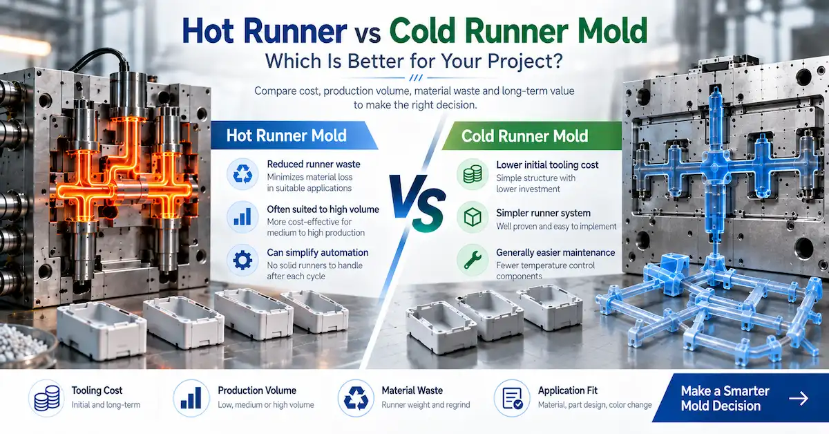
An injection mold cooling system should remove heat from the cavity and core as evenly as the part geometry allows. The goal is not simply to circulate water through the mold. A useful cooling design balances heat transfer, pressure drop, temperature uniformity, access for maintenance, interference with ejectors and inserts, and the production cycle required by the part.
For OEM engineers and tooling buyers, the practical question is: will the proposed cooling layout give a stable cycle and acceptable part geometry for this resin, wall structure, cavity count, and application? A channel layout that looks complete in a 3D assembly can still leave hot spots near bosses, ribs, deep cores, slides, or thick sections. Those thermal differences can contribute to sink, shrinkage variation, flatness problems, dimensional drift, and warpage.
Need your cooling layout reviewed against the part CAD? Share the latest model, material grade, annual volume, critical dimensions, target machine, and known hot-spot or warpage concerns before the mold design is released.
Request a Tooling and Cooling Review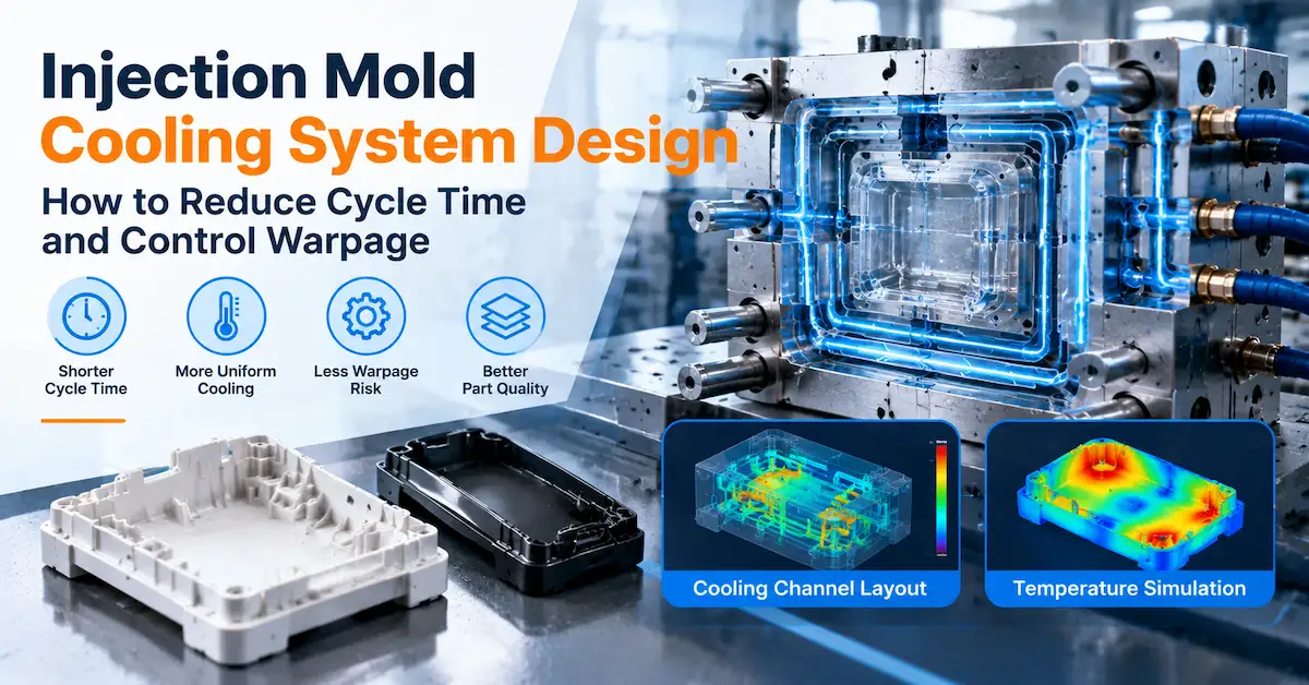
What Is an Injection Mold Cooling System?
An injection mold cooling system is the network and hardware used to control heat inside the mold during injection molding. It usually includes drilled or machined cooling channels in the cavity and core, connections and manifolds, plugs or fittings, baffles or bubblers for deep areas, cooling around inserts where feasible, and a temperature-control circuit. The final design depends on the mold structure, part geometry, resin, production machine, safety requirements, and maintenance plan.
During a molding cycle, hot polymer enters the cavity and transfers heat into the steel. The mold must remove enough heat for the part to reach the required ejection condition while keeping the cavity surfaces sufficiently uniform. If one region remains hotter than another, the part can continue shrinking unevenly after ejection. If cooling is too aggressive or poorly balanced in another region, the part may freeze earlier, pack differently, or develop a different surface and dimensional response.
The cooling system therefore has two jobs:
- Thermal removal: carry heat away from the cavity, core, inserts, and other tool regions.
- Thermal uniformity: keep the mold and molded part from developing avoidable hot-to-cold differences.
These goals can conflict. A dense channel pattern may improve local heat removal but reduce steel strength, interfere with ejectors, or complicate manufacture and maintenance. A simple pattern may be easier to build but leave a thick boss or deep core too hot. The design review should justify complexity against quality and cycle-time benefit.
Cooling is part of the product decision
Cooling should be reviewed together with wall thickness, ribs, bosses, texture, gate location, parting line, ejection, material shrinkage, and assembly requirements. It is not a hidden mold-base detail that can be approved after the product design is fixed. A thick section behind a visible panel may create a cosmetic risk. A deep core may control the cycle even if the rest of the part is thin. A cooling connection may be easy to install but impossible to service after a slide or hose is added.
The buyer should mark the product areas that matter most:
- Cosmetic surfaces where sink, gloss change, or distortion is unacceptable.
- Flatness, sealing, connector, snap-fit, and mating surfaces.
- Thick bosses, ribs, pads, battery pockets, and local mass.
- Deep cores, narrow slots, slides, lifters, inserts, and other difficult-to-cool regions.
- Critical dimensions and datums used for CMM or other inspection.
- Areas where cycle time limits output or where the part must be ejected at a controlled temperature.
How Cooling Layout Affects Cycle Time
Cycle time is the time required to complete one molding cycle. It normally includes mold closing, filling, packing or holding, cooling, mold opening, and part ejection or removal. The exact sequence and duration depend on the machine, material, part, mold, automation, and approved process conditions. Cooling is only one part of the cycle, but it often becomes a major constraint when a part has thick sections, deep cores, poor thermal access, or a high required ejection temperature.
Reducing cycle time by simply increasing flow or lowering the ejection temperature can create a quality problem. The part may leave the mold while it is still too soft, allowing shrinkage or deformation during handling. A better approach is to identify the thermal bottleneck and decide whether it should be addressed through geometry, channel placement, insert design, mold-temperature control, process tuning, or a different production strategy.
Where cooling time comes from
Cooling time is influenced by the thickest effective section, the resin's thermal behavior, the mold surface temperature, the cooling-medium temperature, the heat-transfer path through the steel, the channel layout, and the ejection requirement. A thin wall surrounded by a large hot boss does not cool like an isolated thin wall. A deep core may have a longer heat path than a shallow cavity surface. An insert may conduct heat differently from the surrounding mold steel.
For a buyer, the useful request is not a universal promised cooling time. Ask the supplier to identify the assumed cycle drivers and the evidence used to validate them. The quotation or tooling review should make clear whether cycle time is a preliminary estimate, a trial target, a production requirement, or a guaranteed contractual value. These are different commitments.
Cooling layout and heat-transfer path
A channel is effective only when heat can travel from the part surface through the mold material to the cooling medium. The distance, orientation, diameter, circuit length, steel thickness, insert boundaries, and local geometry all affect that path. A channel far from a hot spot may have plenty of water flow and still provide limited local cooling. A channel placed too close to the cavity may weaken the steel, create a surface risk, or leave insufficient material for machining and maintenance.
Review the layout in section views, not only in a shaded 3D model. Section views expose the distance from the molded surface to the channel, intersections with ejector holes, plugs, slides, lifters, inserts, and the remaining steel around the cavity. They also help the buyer understand whether the proposed circuit can actually be drilled, plugged, cleaned, connected, and inspected.
Flow distribution and circuit design
Cooling circuits should be evaluated for temperature distribution, flow path, pressure loss, connections, and maintenance. A long or poorly arranged circuit may experience a temperature rise along the route, so the first and last regions do not receive identical thermal conditions. Separate circuits may be more useful than one long path when the core and cavity have different thermal loads or when a hot spot needs independent adjustment.
Do not judge a design only by the number of channels. A meaningful review asks which circuit serves each region, how the inlet and outlet are identified, whether flow can be measured or balanced, and how the circuit will be flushed or repaired. The correct design depends on the mold's actual structure and the buyer's maintenance practices.
| Cycle-time driver | Cooling-system question | Evidence to request |
|---|---|---|
| Thick section or local mass | Where does the heat leave the region, and is the channel close enough without weakening the steel? | Section view, thermal-risk map, and cooling-circuit rationale |
| Deep core or narrow feature | Is a baffle, bubbler, insert circuit, or other solution required? | Core section, component detail, service plan, and trial observation |
| Large flat surface | Is cooling distributed well enough to control temperature variation and flatness? | Channel map, warpage-risk review, and flatness inspection plan |
| Multi-cavity tool | Are cavities exposed to comparable thermal conditions and adjustable circuits? | Cavity-by-cavity circuit map and sample traceability plan |
| High-output program | What cycle assumption is being used, and how will it be validated without sacrificing part quality? | Trial parameter record, ejection condition, and production acceptance criteria |
Cooling Layout Principles for Mold Design
A reliable injection mold cooling system is designed around the part's thermal map. The layout should follow the regions that create or retain heat while respecting the mechanical structure of the mold. The following principles are useful during DFM and mold-design approval.
1. Keep cooling reasonably close to the molded surface
Closer channels can improve heat transfer, but “closer” is not automatically better. The designer must leave enough steel for cavity strength, machining, polishing, wear, corrosion, plugs, and future repair. The correct distance depends on local pressure, steel grade, feature shape, channel size, and the mold structure. Ask for sections through critical areas instead of accepting a general statement that the water lines are optimized.
2. Follow the part geometry, not only the mold outline
A rectangular channel pattern may work for a simple plate but perform poorly around a curved housing, deep boss, angled wall, or irregular insert. Where conventional drilling cannot follow the part, the design may need inserts, baffles, bubblers, thermal pins, conformal features, or a geometry change. The right choice depends on the part value, production volume, steel, tooling budget, and maintenance requirements.
3. Address hot spots near bosses, ribs, and thick sections
Internal ribs and bosses can add material behind an exterior wall. If the design does not core out the mass or provide a reasonable heat path, the region may cool more slowly and create sink or read-through. Cooling cannot fully correct poor wall-thickness design. The DFM review should therefore consider the wall, rib, boss, gate, and cooling layout as one system.
4. Separate cavity and core thermal needs
The cavity and core often see different surface areas, materials, and heat loads. A symmetrical-looking layout can still produce asymmetric thermal behavior. Review the cavity-side and core-side circuits separately, identify independent adjustment points, and check whether hoses or fittings interfere with mold installation, automation, or safety guarding.
5. Design around slides, lifters, and inserts
Moving structures and replaceable inserts can block a straight channel or create an isolated hot region. Cooling design must leave room for movement, guides, seals, fasteners, wear plates, ejectors, and maintenance. If a slide is hot, the designer should explain whether it receives a dedicated circuit, a thermal insert, or an accepted process limitation. Do not assume that a visible water connection proves the moving feature is adequately cooled.
6. Make circuits identifiable and serviceable
Inlet and outlet markings, circuit numbering, accessible fittings, plugs, sealing details, drain paths, and cleaning access matter after the mold leaves the toolmaker. A cooling system that is difficult to connect or flush can create avoidable downtime. Include the cooling layout and circuit identifiers in the mold documentation and handover package.
How Cooling Imbalance Causes Warpage
Warpage is a shape change that occurs when different regions of the molded part shrink or relax by different amounts. Cooling imbalance is one contributor, but it is not the only one. Part geometry, material shrinkage, fiber orientation, packing, gate location, ejection, mold temperature, and process conditions can all influence the final result.
The basic risk is straightforward: if one side or region of a part remains hotter for longer, it may shrink differently from a cooler region. A flat panel can bow. A housing can twist. A flange can lift. A hole can move relative to a datum. A sealing edge can lose flatness. In a multi-cavity tool, different thermal conditions can create cavity-to-cavity differences even when the nominal geometry is identical.
Cooling imbalance versus part-design imbalance
Not every warpage problem is a cooling-channel problem. A part with non-uniform wall thickness, a large boss directly behind a cosmetic wall, a constrained insert, or a long fiber-filled flow path may warp even with a well-designed cooling system. The investigation should separate the possible causes:
- Geometry: wall-thickness transitions, ribs, bosses, corners, radii, and constrained features.
- Material: resin grade, filler, shrinkage behavior, moisture, and processing window.
- Filling and packing: gate location, flow length, weld lines, pressure distribution, and gate freeze.
- Thermal design: channel location, circuit balance, mold-temperature difference, and local hot spots.
- Ejection: timing, support, force distribution, and deformation while the part is still warm.
- Measurement: datum choice, conditioning time, fixture restraint, and inspection method.
This is why an injection mold cooling system should be reviewed with Mold Flow and DFM evidence where that scope is agreed. A simulation can help compare filling, packing, cooling, and warpage assumptions, but the result is not a substitute for physical samples. It should be treated as an engineering prediction that needs to be confirmed against the approved resin, tool, process, and inspection method.
Warpage-control actions before steel cutting
Before steel is cut, the team can compare several levers:
- Improve wall-thickness uniformity or core out excessive mass.
- Adjust the gate location or gate count to improve packing and flow balance.
- Move or separate cooling circuits around hot spots and thick features.
- Add cooling to a deep core, insert, slide, or lifter where the structure allows it.
- Review resin grade, filler direction, and shrinkage input.
- Define an ejection condition that does not deform the part while it is too warm.
- Agree the measurement method, conditioning time, fixture, and warpage limit.
Do not approve a “warpage correction” that changes the product geometry without documenting whether the change is a steel-safe adjustment, a mold correction, a process adjustment, or a product-design revision. The buyer should know which CAD revision and acceptance requirement the correction belongs to.
Cooling Strategies by Part Geometry
| Part condition | Main thermal risk | Cooling review focus |
|---|---|---|
| Thin flat cover | Temperature difference across the surface can affect flatness and gloss | Even circuit spacing, cavity/core balance, gate and packing relationship |
| Housing with bosses and ribs | Local mass retains heat and can create sink or read-through | Core-out, boss cooling, rib layout, visible-face inspection |
| Deep core or tube | Long heat path and limited access for straight drilling | Baffle, bubbler, insert, thermal pin, or alternate core strategy |
| Large automotive or appliance panel | Long flow path and broad-surface temperature variation | Multiple balanced circuits, support steel, warpage map, and trial fixture |
| Glass-filled structural part | Cooling and fiber orientation can combine to create directional shrinkage | Gate direction, load path, resin grade, cooling symmetry, validation method |
| Multi-cavity precision part | Cavity-to-cavity temperature and shrinkage variation | Circuit identification, cavity traceability, CMM plan, and process records |
What a Tooling Buyer Should Approve in the Cooling Design
A cooling layout should be approved as a controlled engineering deliverable. The buyer does not need to design every channel, but should understand the assumptions and accept the risks that affect the product. The following items should be visible in the review package.
Cooling layout and section views
Request cavity-side and core-side cooling layouts, circuit numbers, inlet and outlet identification, section views through hot spots, and clearance checks around ejectors, slides, lifters, inserts, fasteners, and the parting line. A 3D picture without section views makes it difficult to judge the real heat-transfer path and remaining steel.
Material and process assumptions
The cooling decision depends on the actual resin grade and process window. The public Supports page lists material consultation for examples including ABS, PC, PP, PA66, medical-grade and food-grade materials, and mentions shrinkage rate, temperature resistance, flame-retardant grade, certification introduction, and alternative-material cost comparison. These are website-listed support topics, not confirmation of a specific grade, supplier, certification, or regulatory approval for a project.
Include the resin grade, filler, color, moisture requirement, mold-temperature range, expected quantity, machine, and critical quality features in the RFQ. If these inputs are still open, label them as assumptions and identify which parts of the cooling and warpage decision may change when they are confirmed.
Manufacturing and maintenance feasibility
Cooling channels must be machined, plugged, pressure-tested, connected, and maintained. Ask how the supplier will verify circuit continuity and leakage, how the operator will identify each connection, whether channels can be cleaned, and whether a blocked circuit can be diagnosed after the mold is transferred. Also check access around slides, hot-runner components, ejector systems, and mold-base connections.
Cooling-related handover documents
A useful handover package may include the approved cooling layout, circuit list, connection map, component or plug information, test records, maintenance instructions, and trial parameter records. The exact document set must be agreed in the quotation. Do not assume that a supplier's standard package includes the same cooling drawings or test data for every project.
How Cooling Is Validated During Mold Trials
Cooling design is validated through both the mold and the molded part. The tool can have a plausible channel layout and still need adjustment after the first trial. The part can meet a nominal dimension at one condition and move outside the requirement when the cycle, mold temperature, or material condition changes. Trial validation should therefore connect thermal conditions, process parameters, cavity identity, inspection time, and the observed result.
T0: confirm circuits and baseline behavior
At T0, confirm that the cooling circuits are connected to the correct inlets and outlets, that the mold can run without leakage or interference, and that the basic part can be filled, ejected, and handled. Record the initial temperature, pressure, flow, cycle, material, cavity, and visible defects when those values are part of the agreed trial scope. A T0 sample is a baseline, not automatic proof of production readiness.
T1: compare cycle, dimensions, and warpage
At T1, compare the actual cycle and ejection condition with the approved target or assumption. Inspect critical dimensions, flatness, fit, appearance, sink, and warpage. Use CMM data where the part features and inspection plan make it appropriate. Record the measurement time after molding and whether a fixture or conditioning period was used, because a warm unrestrained part can behave differently from a conditioned sample.
T2 or final validation: check repeatability and closure
Later trials should confirm that cooling changes, process changes, or geometry corrections close the documented risk. For multi-cavity tools, identify samples by cavity. For parts with a warpage limit, use the same datum, fixture, measurement method, and acceptance condition across trial stages. A final report should identify the tool revision, material, process parameters, cycle time, cooling condition, inspection results, open issues, and approval status.
DX Molding's public Supports page lists T0/T1/T2 mold trial reports, dimensional inspection and appearance-defect records, CMM data, modification-plan follow-up, and injection-molding parameter records including temperature, pressure, packing, and cycle time. These are published support capabilities. Confirm which records, instruments, sampling, and acceptance criteria are included in the specific project.
Have a cycle-time or warpage concern? Send the cooling layout, part CAD, resin grade, trial condition, and dimensional or visual evidence so the issue can be separated into geometry, material, process, ejection, or thermal causes.
Review Cooling and Trial SupportIllustrative Cooling Design Cases
The following examples are engineering decision models created for this article. They are not named customer cases, measured DX Molding results, or guarantees of cycle time or warpage performance.
Case 1: Plastic electronics housing with a hot boss zone
A two-piece housing has a thin outer wall, several internal screw bosses, and a connector opening. The first cooling layout follows the outer perimeter but leaves the boss cluster relatively far from a cooling circuit. The visible symptom at trial is a shallow depression near the exterior wall and a longer cycle used to protect ejection.
The correct review does not immediately lower the cycle. It checks whether the boss can be cored out, whether the rib and boss geometry creates local mass, whether the gate and packing path reach the zone, and whether an insert or dedicated cooling feature can be added without weakening the steel. The acceptance plan should inspect the visible surface, boss location, screw fit, and flatness using the approved method.
Case 2: Large panel with edge lift after ejection
A broad appliance or automotive-style panel shows edge lift after ejection. The cavity and core have cooling, but one side has a slide and a different steel thickness. The part appears acceptable immediately after molding and moves later during handling. Possible causes include thermal imbalance, non-uniform wall structure, packing direction, ejection support, or measurement timing.
The investigation should compare the cavity and core temperature condition, circuit flow path, slide cooling, ejection timing, gate and packing assumptions, and the fixture used for flatness measurement. A channel change may be part of the solution, but the team should not label it a cooling defect until the competing causes are checked and the trial evidence supports the conclusion.
Injection Mold Cooling System RFQ Checklist
Use this checklist when requesting a tooling quote or approving a mold-design review. It is intended to make cooling assumptions comparable between suppliers.
| No. | Buyer input or question | Why it matters | Evidence or output |
|---|---|---|---|
| 1 | Latest 3D CAD and controlled 2D drawing | Cooling follows actual wall, rib, boss, insert, and critical-feature geometry | Reviewed product revision |
| 2 | Resin grade, filler, color, and shrinkage input | Thermal and dimensional behavior changes with material | Material assumption record |
| 3 | Expected quantity and cavity target | Cycle, balance, maintenance, and cooling complexity depend on production plan | Cavity and production concept |
| 4 | Cosmetic, flatness, sealing, and assembly surfaces | Thermal variation can become a visible or functional defect | Quality map and acceptance criteria |
| 5 | Cooling layout with section views | Shows heat-transfer path, steel clearance, and interference risks | Cavity/core channel drawings |
| 6 | Circuit identification and connection plan | Supports setup, balancing, maintenance, and troubleshooting | Circuit map and handover list |
| 7 | Cooling and warpage analysis scope | Clarifies whether results are simulation, engineering estimate, or trial evidence | Mold Flow or risk-review deliverable |
| 8 | Cycle-time target and ejection condition | Prevents a low cycle target from being treated as a quality result | Trial parameter record and approval rule |
| 9 | CMM, flatness, and appearance inspection plan | Makes warpage and dimensional comparisons repeatable | Inspection method and report |
| 10 | Open thermal risks and correction ownership | Assigns responsibility before a trial issue becomes a schedule dispute | Risk register and closure record |
What Should a Cooling-System Supplier Prove?
A supplier should be able to explain how the cooling concept connects to the part, mold structure, production requirement, and validation plan. For a serious tooling RFQ, ask for:
- Cooling layouts for cavity, core, inserts, slides, lifters, and other relevant structures.
- Section views through thick areas, hot spots, deep cores, bosses, ribs, and critical flat surfaces.
- Cooling-circuit numbering, inlet/outlet identification, and connection or maintenance information.
- Cooling and warpage analysis scope, assumptions, and report format when Mold Flow is included.
- Cycle-time assumptions, ejection condition, and the difference between an estimate and a validated result.
- T0/T1/T2 trial records with temperature, pressure, packing, cycle-time, dimensional, and appearance data where agreed.
- Cavity-level sample identification for multi-cavity tools.
- Modification plans that distinguish cooling changes from geometry, process, material, and ejection changes.
DX Molding's public website describes Shenzhen DongXin Technology Co., Ltd. as a Shenzhen-based company founded in 2007. It lists custom plastic injection molds, plastic molding, silicone tooling, and OEM/ODM development, and its Supports page describes engineering and DFM review, Mold Flow analysis, optimized cooling-channel layout, machining and trial support, inspection, packaging, and after-sales support. The same page lists photos and videos of key production nodes, weekly progress reporting, T0/T1/T2 reports, CMM data, and parameter records. These are website-stated capabilities; they should be confirmed in the quotation and project evidence for the specific tool.
The public site does not establish one universal cooling-channel diameter, flow rate, coolant temperature, cooling time, cycle-time guarantee, warpage limit, or percentage improvement for every mold. Do not insert those numbers into a purchase order unless they are agreed for the project and tied to a defined material, machine, tool revision, sample condition, and inspection method.
Frequently Asked Questions About Injection Mold Cooling Systems
Why is an injection mold cooling system important?
It removes heat from the mold and helps the part reach the required ejection condition. A balanced system can support more stable cycle conditions and reduce avoidable thermal differences that contribute to sink, dimensional variation, and warpage. Cooling is only one part of the result; geometry, material, gate, packing, ejection, and measurement also matter.
Does better cooling always mean a shorter cycle time?
No. Better cooling means more appropriate heat removal and temperature control for the part and process. A shorter cycle may deform a part if ejection occurs while it is too warm, or may create a different appearance and dimensional result. Validate cycle time together with ejection condition, critical dimensions, flatness, appearance, and repeatability.
How does cooling system design control injection molding warpage?
It helps control thermal differences between regions of the cavity and core. More uniform thermal conditions can reduce one source of differential shrinkage, but warpage can also come from wall-thickness variation, fiber orientation, gate and packing balance, ejection, resin behavior, and part constraints. A cooling change should be evaluated against those competing causes.
What is the best cooling-channel layout for a plastic housing?
There is no universal layout. A housing should be reviewed around its walls, ribs, bosses, deep cores, connector openings, cosmetic surfaces, parting line, and ejection system. The supplier should show cavity and core circuits in section views and explain how hot spots, flatness, gate packing, and maintenance are addressed.
What should I ask for in a cooling-system design review?
Ask for cavity and core cooling layouts, circuit identification, sections through critical areas, interference checks, cooling and warpage analysis scope, material and cycle assumptions, maintenance information, trial parameters, and the measurement plan. Also ask which values are estimates and which will be confirmed by trial.
Can a cooling system fix a poor part design?
Not reliably. Cooling can help manage heat, but it cannot eliminate the consequences of severe wall-thickness changes, excessive boss mass, unsuitable draft, poor gate placement, or a material choice that does not fit the application. DFM should review the part geometry and cooling concept together before steel cutting.
Does CMM inspection prove that warpage is controlled?
CMM data can verify defined points and features when the datums, fixture, conditioning, and method are appropriate. It does not alone prove that a broad surface is visually acceptable, that the part will assemble, or that the result is stable at production conditions. Combine dimensional data with flatness, appearance, assembly, and process records.
What materials and tooling support are relevant to cooling?
Material grade, filler, shrinkage, mold-temperature requirements, steel, inserts, and production quantity all influence the design. DX Molding's public support information lists material consultation topics including ABS, PC, PP, PA66, medical-grade and food-grade examples, and lists mold steels including S136, NAK80, P20, and 718H. Confirm the actual material grade, steel, and project-specific requirements before approval.
Conclusion
An injection mold cooling system is a product-quality and production decision, not merely a set of water lines inside the mold. The layout must remove heat from the cavity, core, inserts, deep features, and local masses while preserving steel strength, mold movement, ejection, service access, and process control.
For cycle-time control, identify the real thermal bottleneck and validate the ejection condition instead of chasing a shorter number in isolation. For warpage control, separate cooling imbalance from geometry, material, gate, packing, ejection, and measurement causes. For supplier selection, require section views, circuit maps, analysis assumptions, trial records, CMM or other dimensional evidence where appropriate, and a clear risk-closure process.
DX Molding's website presents engineering, DFM, Mold Flow, cooling-layout, mold-trial, inspection, and project-support capabilities for custom molding programs. The exact cooling design, cycle-time target, warpage limit, documentation, and acceptance criteria must be agreed for the specific part and tool. Start the review with the controlled CAD, resin grade, volume, critical surfaces, target machine, and the quality evidence needed for production approval.
Ready to review your injection mold cooling system?
Share your CAD revision, resin, annual volume, target cycle, critical dimensions, and warpage or hot-spot concerns.
Discuss Your Cooling and Tooling Requirements