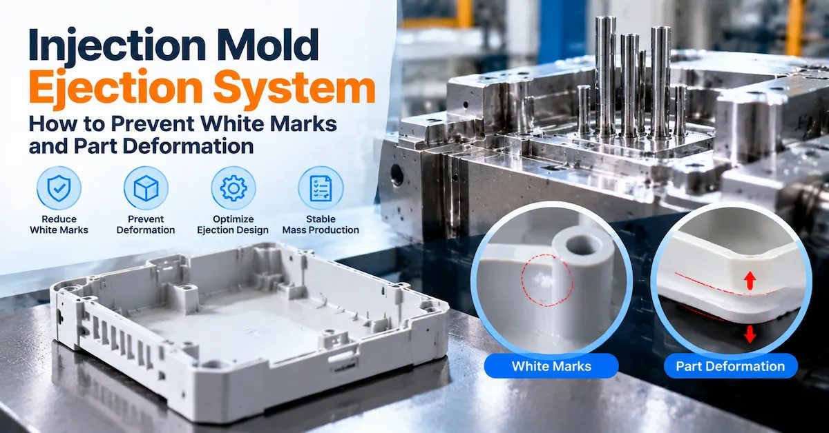
An injection mold ejection system should release the molded part with distributed, controlled force while protecting appearance, dimensions, and assembly features. If the system is too concentrated, poorly supported, or activated while the part is still too hot, the result can be white marks, drag marks, stress whitening, pin impressions, bending, twist, or a part that no longer fits the next assembly.
For an OEM buyer, the key question is not simply whether a mold has ejector pins. The useful question is whether the proposed ejection method matches the part geometry, resin, draft, texture, cooling condition, cosmetic zones, undercuts, and production requirements. This guide explains how to compare ejector pins, ejector sleeves, lifters, stripper plates, air-assisted release, and combined layouts, then shows how to investigate white marks and injection molded part deformation before approving tooling.
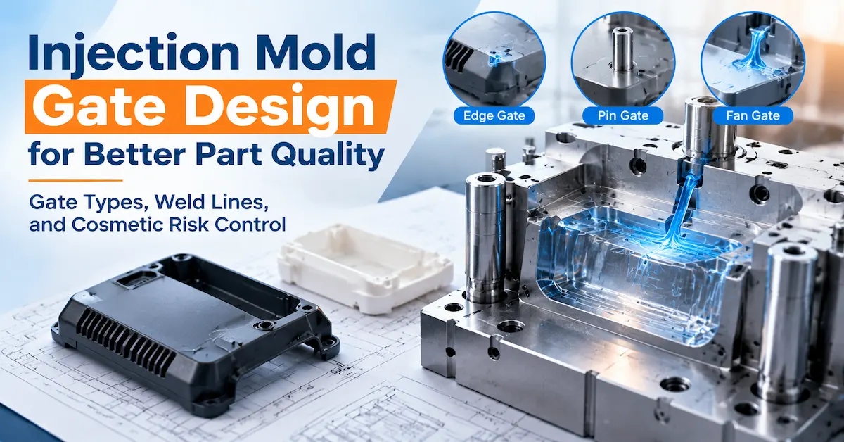
DX Molding's published custom plastic mold service information lists ejector pins, angle lifters, slides, stripper plates, cooling channels, parting-line design, single-cavity and multi-cavity structures, and several mold-steel options as part of its mold engineering scope. The website also describes T0/T1/T2 trial reporting, dimensional inspection, CMM data, parameter records, and modification follow-up. These are public capability descriptions; the actual ejection layout, force, component sizes, inspection method, and acceptance criteria must be confirmed for the specific mold.
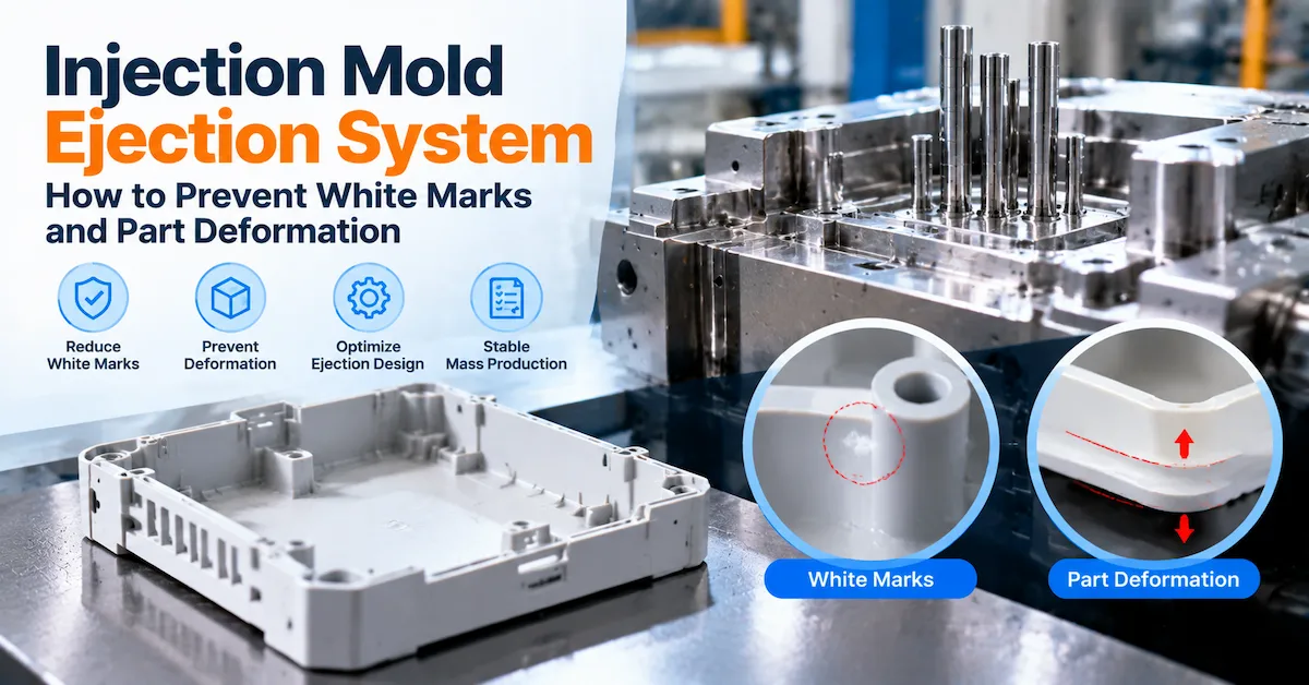
What Is an Injection Mold Ejection System?
An injection mold ejection system is the group of mold components and process actions that separates the cooled or partially cooled molded part from the core after the mold opens. It normally includes an ejector plate or plates, return pins, ejector pins, sleeves, lifters, stripper elements, guide components, and the machine-side ejection connection. Depending on the geometry, the mold may also use air to break a vacuum, a slide or insert to release an undercut, or a special mechanism for threaded or otherwise trapped features.
The ejection system has four related jobs:
- Release: overcome adhesion, shrink-fit, texture drag, vacuum, and friction between the part and core.
- Support: distribute the force so thin walls, ribs, bosses, and cosmetic faces do not bend or mark.
- Protect: avoid unacceptable pin marks, whitening, scratches, distortion, flash, or damage to sealing and assembly features.
- Repeat: release the part consistently across cycles, cavities, material lots, and normal process variation.
These jobs can conflict. A large flat panel may need many support points to prevent bending, but every additional pin creates a possible mark and requires space in the mold. A tall boss may need a sleeve or a pin close to its base, but the same location may interfere with a cooling channel, insert, lifter, or return component. The best ejection design is therefore a coordinated mold decision, not a standard pin pattern copied from another project.
How to Choose the Ejection Method
The right method depends on where the part grips the core, where force can be applied, what surfaces are visible, and how much movement the tool requires. The following comparison is a design framework, not a universal product configuration.
| Ejection method | Where it can help | Main buyer question |
|---|---|---|
| Ejector pins | General parts, ribs, internal walls, and areas where discrete support points can be hidden. | Are the pin locations supported by enough steel and kept away from visible or sealing surfaces? |
| Ejector sleeves | Bosses, posts, and circular features where a ring of force is more useful than one central pin. | Will the sleeve support the feature without creating a ring mark, flash, or interference with a core pin? |
| Angle lifters | Internal undercuts, hooks, or features that need a combined lifting and side-release movement. | What feature requires the lifter, and how will its movement avoid rubbing or deforming the part? |
| Stripper plate | Parts needing broad, relatively even release around a perimeter or large surface. | Can the plate move evenly without damaging the parting edge, texture, or appearance? |
| Air-assisted release | Parts with vacuum or adhesion risk where air can help break the part away from the core. | Where is the air introduced, and does the method change contamination, cycle, or process-control requirements? |
| Combined layout | Complex parts where different regions need different release and support strategies. | Is every mechanism necessary, serviceable, and validated in the same ejection sequence? |
Ejector pins for general release
Ejector pins are often the simplest way to apply force from the back of a molded part. They work well when the pin can contact a structurally supported internal surface and when the resulting mark is hidden or acceptable. They become risky when a small pin is asked to push a large, flexible panel, a thin rib, a soft part, or a cosmetic surface.
Review the contact area, pin quantity, spacing, support under the part, pin return, wear, and access for maintenance. A pin placed directly under a thin cosmetic wall may leave a circular impression even when the mold is machined accurately. A pin near a rib may be structurally useful but can also create a local stress point if the rib is too thin or the part is ejected before it has enough stiffness.
Ejector sleeves around bosses and posts
A sleeve can apply force around a cylindrical boss or post, which may reduce the concentration associated with a single pin. It is not automatically safer. The sleeve must have suitable clearance, guidance, draft, and support, and it must not damage the boss edge or create a visible ring. If a core pin runs through the feature, the relationship between the core pin and sleeve must be checked through the full stroke.
Lifters and slides for undercuts
A lifter or slide may be required because the product has an undercut, internal hook, side opening, or locking feature. It is not simply an ejector with a different name. The mechanism must release the trapped feature before or during ejection without dragging across the part. The buyer should ask why the movement is needed, whether a product change could simplify it, which components wear, and how the mechanism will be inspected and serviced.
Stripper plates for broad and even release
A stripper plate can distribute release force over a larger perimeter or surface, which may be useful for ring-shaped, thin-walled, or appearance-sensitive parts. Its edge must be designed around the parting line, draft, texture, and any thin lip. Uneven plate movement can produce a different kind of deformation than a pin system, so guide, balance, and clearance checks are essential.
Part Features That Control Ejection Risk
Before approving the mold structure, mark the surfaces that the part grips and the surfaces that can safely receive force. The same mold may need different ejection logic for its cavity side, core side, inserts, slides, and lifters.
Draft angle and texture
Insufficient draft increases the force required to pull a part over the core. Texture can increase mechanical drag, especially on deep walls, ribs, pockets, and shutoff-adjacent surfaces. When a part shows whitening or drag, the first question should be whether the part is being forced across a surface that it cannot release from cleanly.
The drawing should identify the pull direction and the faces requiring texture or polish. The supplier should review draft against the actual finish rather than treating a polished face and textured face as equivalent. A fixed draft number should not be copied to every surface without considering depth, resin, shrinkage, texture, and ejection temperature. These release conditions belong in the broader injection mold DFM and CAD review before steel cutting.
Ribs, bosses, and deep pockets
Ribs and bosses create both structural support and release challenges. A rib can grip the core if its draft is limited or if it shrinks around a steel feature. A boss can cling to a core pin and require a sleeve, a pin, or a different release direction. Deep pockets can create vacuum and can remain hotter than the surrounding wall.
For these areas, check:
- Draft on both sides of the feature.
- Local wall thickness and shrink-fit around steel.
- Distance between the feature and the nearest ejection support.
- Whether the ejection contact is on a rib, boss, flat pad, or thin skin.
- Whether cooling is sufficient before the part is pushed.
- Whether an ejector mark will be visible after assembly.
Large flat panels and thin skins
Large panels are sensitive to uneven force. A pin layout concentrated near the center can push the middle out while the edges remain attached. Pins concentrated near one side can twist the panel. A panel may also warp because of differential shrinkage, so changing the pins alone may not solve the problem.
For a broad panel, review the release sequence, support points, venting or vacuum risk, cooling balance, gate and packing behavior, and the condition of the part at ejection. Define a flatness or profile method before the trial. “Looks flat” is not a repeatable acceptance criterion.
Why Ejection Causes White Marks
White marks, whitening, and stress whitening can appear when the plastic is stretched, compressed, or rubbed beyond what the local material and geometry can tolerate. The mark may be directly over an ejector, beside a rib, at a draft transition, around a textured wall, or near a trapped feature.
Common contributors include:
- High release force caused by insufficient draft or texture drag.
- Too much force applied through too few or too-small ejector contacts.
- Part ejected while still too hot or too flexible.
- Unbalanced pin timing, plate movement, or lifter motion.
- Sharp corners or thin sections near the ejection contact.
- Vacuum between the part and core.
- Core or cavity surface damage, contamination, or excessive friction.
- Material orientation, filler, moisture, or process conditions that make whitening more visible.
How to distinguish whitening from other defects
A white circular mark aligned with an ejector location suggests an ejection contact or local stress issue, but location alone is not proof. A pale line following the flow path may be a weld-line or flow-related mark. A shallow depression opposite a boss may be sink. A cloudy area that changes with lighting may be a surface or material condition.
Use a controlled diagnosis:
- Record the exact location, size, cavity, orientation, and lighting condition.
- Compare the mark with the ejector, sleeve, lifter, parting line, gate, rib, and boss layout.
- Check whether the mark appears immediately after ejection or develops after cooling.
- Inspect draft, surface finish, steel condition, venting, and ejection alignment.
- Compare samples at different ejection temperatures or cooling conditions without changing several variables at once.
- Confirm whether the mark affects appearance only or also changes fit, strength, sealing, or assembly.
Ways to reduce ejector whitening
Potential corrections should be selected after the failure mechanism is confirmed. The mold engineer may increase effective draft, improve the surface finish, move or add support, use a sleeve or stripper approach, enlarge or redistribute contact area, correct lifter alignment, add a vacuum-break feature, or adjust the ejection sequence. Process changes may include allowing more cooling or changing the release condition, but a process adjustment should not hide a fundamentally poor ejection layout.
Do not promise that one change will remove every white mark. A supplier should state which hypothesis is being tested, what sample evidence will be collected, and what acceptance limit applies. The public DX Molding support information does not publish a universal white-mark limit or an improvement percentage, so those values must be defined for the project.
Why Ejection Causes Part Deformation
Deformation occurs when the release force, temperature, geometry, and shrinkage are not balanced. A part may bend as it leaves the core, twist because one region releases first, or continue to deform after ejection because it is still soft. It may also be dimensionally out of shape before ejection because the mold temperature, cooling, gate location, packing, or material behavior created differential shrinkage.
| Observed deformation | Possible ejection-related cause | Verification method |
|---|---|---|
| Panel bends near the center | Central pins move the panel while the perimeter still grips, or the panel is too hot at release. | Compare pin map, release sequence, ejection temperature, and flatness immediately after release. |
| Part twists toward one corner | Uneven pin contact, plate tilt, asymmetrical draft drag, or unbalanced cooling and shrinkage. | Check ejector plate travel, pin contact, cavity balance, and dimensional map by cavity. |
| Boss leans or cracks | Side load on a boss, release around a core pin, insufficient support, or a hot and weak feature. | Inspect sleeve or pin alignment, boss draft, core condition, and assembly load. |
| Thin wall pulls or folds | Insufficient support, vacuum, early release, or ejection force applied at a weak section. | Review venting, support area, mold opening, ejection timing, and part temperature. |
| Part springs back after release | Residual stress, fiber orientation, differential shrinkage, or release from a constrained core. | Measure at defined conditioning times and compare process, material, and mold-layout evidence. |
Separate ejection deformation from molding warpage
This distinction matters. If the part is already warped before the ejector moves, the main cause may be cooling, packing, gate location, wall thickness, material orientation, or mold-temperature imbalance. If the part changes shape during or immediately after ejection, the ejection system, release force, support, vacuum, or part temperature deserves priority.
Use a time-based observation: inspect the part before ejection if the process allows it, immediately after release, after a controlled cooling interval, and after assembly. The location and timing of the change provide more useful evidence than a general statement that “the mold is deforming the part.”
Ejection Layout Checks Before Steel Cutting
Before mold manufacturing begins, the ejection concept should be visible in the mold design and section views. The buyer does not need to approve every component dimension without engineering review, but should be able to understand how the part will be released and where marks or force will occur. The ejection proposal should also be reviewed as part of the complete plastic injection mold, not as an isolated component list.
Force distribution and support
Map the areas that resist release and the areas that can accept force. Put support near ribs, bosses, thick pads, and strong internal surfaces, but avoid creating an ejector pattern that telegraphs onto visible faces. A broad part may need a mix of pins, sleeves, and stripper support rather than many identical pins.
Return, alignment, and maintenance
Check that the ejector plate returns fully, that pins do not remain proud, and that the mechanism is guided through the full stroke. Misalignment can cause pin wear, galling, drag, flash, or incomplete return. Ask how the ejection system will be cleaned, lubricated, inspected, and repaired after repeated production.
Interference with cooling and moving components
Ejector pins, sleeves, lifters, slides, inserts, cooling channels, screws, and support pillars compete for space. A pin layout that looks reasonable on the part may be impossible to drill or may weaken the steel. Review cross-sections through critical ribs, bosses, deep pockets, and cosmetic panels. The ejection system should be checked at the same time as cooling and side actions, not after those decisions are frozen.
Do not invent universal ejection specifications
The public website does not publish one standard ejector-pin diameter, spacing rule, ejection force, ejection stroke, speed, or white-mark acceptance limit for every tool. These values depend on the part, resin, draft, texture, mold steel, machine, and project acceptance criteria. A quotation should state the project-specific assumptions rather than presenting an industry rule as a DX Molding guarantee.
How Mold Flow, Cooling, and Ejection Work Together
Ejection problems are often symptoms of earlier decisions. A gate that creates uneven packing can leave one region tighter on the core. Cooling that leaves a deep boss hot can make that feature too soft during release. A wall-thickness change can create both shrinkage distortion and local drag. A parting line that traps a feature can force the ejection system to work harder.
DX Molding's public engineering and production support information describes filling, packing, cooling, and warpage analysis, along with review of gate location, weld lines, air traps, and sink-mark risk. For a high-risk part, ask whether the analysis includes the proposed ejection concept and which results will be checked physically. Simulation can identify a likely thermal or flow risk, but it does not replace inspection of the actual mold trial.
Review these relationships before release:
- Gate and packing can change how tightly the part grips the core.
- Cooling balance affects stiffness at the moment of ejection.
- Draft and texture affect the force required to release the part.
- Ribs and bosses determine where support can be applied.
- Slides and lifters may need to release before the main ejector stroke.
- Parting lines and shutoffs can create local drag or flash.
How to Validate an Injection Mold Ejection System
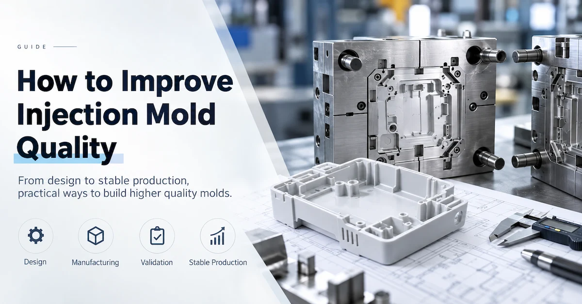
A good-looking first sample is not enough to approve an ejection system. The trial must show that the part releases consistently and remains within the agreed appearance, dimensional, flatness, and assembly requirements. The broader injection mold manufacturing workflow explains how design, machining, assembly, trials, inspection, and modification connect before production release.
T0: confirm mechanism and basic release
At the first trial, observe mold opening, slide or lifter release, ejector plate travel, pin return, part retention, and operator or automation access. Record whether the part sticks, drops, hangs on a feature, or requires manual force. Photograph or map any marks by cavity and location.
T1: diagnose marks and deformation
At T1, compare the sample to the controlled drawing and appearance standard. Review white marks, pin impressions, drag, flash, sink, warpage, flatness, boss position, connector or mating features, and assembly. Keep the material grade and process record tied to each sample so a mold correction is not confused with a process change.
T2 or final validation: confirm repeatability
After corrections, confirm that the part releases without abnormal force and that the result repeats across samples and cavities. For critical dimensions, use the agreed CMM or fixture method. For broad surfaces, add flatness or profile inspection. For an assembly part, use the actual mating components or an approved representative fixture.
Evidence to request from the supplier
DX Molding's public Supports page lists T0/T1/T2 mold trial reports, dimensional inspection, CMM data, modification plans, and injection parameter records including temperature, pressure, packing, and cycle time. Ask which of these documents apply to the project and whether the report identifies mold revision, cavity, resin, process settings, open risks, and corrective actions.
Injection Mold Ejection System RFQ Checklist
Include enough information in the RFQ for the supplier to design the ejection system around the real product. A request that only says “no ejector marks” is incomplete because it does not define where marks are unacceptable, how the part will be inspected, or which surfaces can receive force. Buyers comparing quotations can use the broader injection mold supplier evaluation checklist to align tooling scope, trials, inspection, ownership, and long-term support.
| No. | RFQ input | What to define | Evidence or output |
|---|---|---|---|
| 1 | Part files and revision | 3D CAD, 2D drawing, resin, parting direction, and current revision. | Controlled file list. |
| 2 | Cosmetic zones | Faces that must be free from ejector marks, whitening, drag, flash, or visible parting lines. | Appearance map and limit sample. |
| 3 | Ejection method | Pins, sleeves, lifters, stripper plate, air assistance, or combined approach. | Ejection layout and section views. |
| 4 | Draft and texture | Pull direction, depth, texture, polish, and areas with release risk. | Draft review and surface specification. |
| 5 | Material and process | Resin grade, filler, color, mold temperature, and ejection condition assumptions. | Material and parameter record. |
| 6 | Critical geometry | Ribs, bosses, deep pockets, thin walls, flat panels, undercuts, and sealing surfaces. | Risk map and support rationale. |
| 7 | Cooling and flow | Gate, packing, cooling, hot spots, and possible core adhesion or vacuum. | Analysis scope and cooling layout. |
| 8 | Defect limits | White mark, pin mark, drag, distortion, flatness, flash, and appearance acceptance. | Inspection standard and sample method. |
| 9 | Trial plan | T0/T1/T2 scope, cavity identification, process record, and correction responsibility. | Trial report and action list. |
| 10 | Inspection and assembly | CMM or fixture points, flatness method, mating parts, and functional checks. | Dimensional and assembly approval records. |
What Should an Ejection-System Supplier Prove?
A capable supplier should be able to connect the ejection layout to the actual product risk. DX Molding's custom molding services describe the wider path from project-file review and DFM through mold design, machining, trial approval, and production. For the ejection portion of that scope, ask for an explanation that answers:
- Where does the part grip the core, and where can force be applied?
- Why is a pin, sleeve, lifter, stripper, or air-assisted method chosen for each region?
- Which marks are hidden, which are acceptable, and which are prohibited?
- How do the pins and plates avoid cooling channels, inserts, slides, lifters, and support pillars?
- What happens if the part is still hot, the draft is limited, or the texture increases drag?
- How will white marks and deformation be separated from warpage, sink, weld lines, or material effects?
- Which dimensions, appearance areas, flatness checks, and assemblies will be validated at T0/T1/T2?
- What documents will identify the mold revision, material, cavity, parameters, inspection result, and correction plan?
DX Molding's public custom plastic mold service should be evaluated against the project-specific drawing and evidence package. The public Supports page also describes mold design, ejection components, Mold Flow-related risk analysis, trial reports, CMM data, and modification plans. The published information does not establish a fixed ejection force, universal pin layout, guaranteed cosmetic result, or standard deformation limit.
Frequently Asked Questions About Injection Mold Ejection Systems
What is the best ejection method for an injection mold?
There is no universal best method. Ejector pins are common for general internal surfaces, sleeves can suit bosses, lifters can release undercuts, and stripper plates can distribute force over a broader area. The correct choice depends on the part's draft, texture, shrinkage, cosmetic zones, geometry, and production requirements.
Why does an injection molded part turn white during ejection?
Whitening can result from excessive release force, insufficient draft, texture drag, a hot or flexible part, uneven pin contact, sharp geometry, vacuum, or material and process conditions. Compare the mark location with the ejector layout and check when the mark appears. Do not assume every white mark is caused by the ejector pin.
How can ejector pin marks be prevented?
Reduce the need for concentrated force by improving draft, supporting the part, distributing ejection, moving marks to hidden areas, using a sleeve or stripper approach where appropriate, correcting alignment, and validating the release temperature. The acceptance limit and acceptable mark locations should be defined before the trial.
What causes part deformation during mold ejection?
Common causes include unbalanced force, a part that is too hot, insufficient support, vacuum, uneven draft drag, lifter or slide interference, and differential shrinkage from cooling, packing, gate, wall thickness, or material behavior. Observe when the shape changes to separate ejection deformation from molding warpage.
Are stripper plates better than ejector pins?
Not automatically. A stripper plate can give broad support, but it adds its own requirements for guide accuracy, plate balance, clearance, parting-edge protection, and maintenance. Pins may be simpler and more flexible for internal support. The right method is the one that releases the actual part within its appearance and dimensional limits.
Does a lifter eject the part or only release an undercut?
A lifter can perform both functions in a coordinated motion, but its geometry and timing must be designed for the specific undercut. It should release the trapped feature without rubbing, lifting, or bending the part. The buyer should ask why the lifter is required and how it will be maintained.
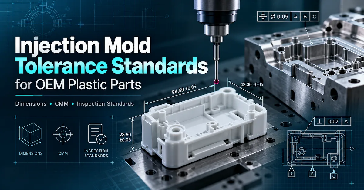
Can CMM data prove that an ejection system is acceptable?
CMM data can verify defined points and features when the datum, fixture, conditioning, and method are appropriate. It does not by itself prove that the part has no visible whitening, that a large panel is flat, or that the assembly works. Combine dimensional data with appearance, flatness, ejection observation, and assembly checks.
What should I send for an injection mold ejection system review?
Send the 3D CAD, 2D drawing, resin and grade, annual quantity, surface finish, cosmetic zones, draft and parting direction, critical ribs and bosses, undercuts, assembly information, flatness or tolerance requirements, and known defects. State whether you need the mold only or molded parts as well.
Does the DX Molding website publish a standard ejection force or white-mark limit?
No universal ejection-force value or white-mark limit is established in the public information reviewed for this article. The website lists relevant mold-design and validation capabilities, but the force, layout, component sizes, process condition, and acceptance criteria must be confirmed for the project.
Conclusion
An injection mold ejection system should be designed around the part's release behavior, not added after the cavity and cooling layout are complete. Ejector pins, sleeves, lifters, stripper plates, and air-assisted release each solve different problems, and a combined system may be necessary for a complex mold.
To prevent white marks, investigate draft, texture, friction, contact area, alignment, temperature, vacuum, and material behavior. To prevent deformation, distinguish force-induced movement during ejection from warpage caused by cooling, packing, gate location, wall thickness, or shrinkage. Then validate the actual result with T0/T1/T2 evidence, dimensional or CMM inspection where appropriate, appearance review, flatness checks, and assembly testing.
DX Molding's published tooling information describes mold engineering and ejection-related structures, together with trial, inspection, parameter-record, and modification support. The final ejection system, tool structure, material, tolerance, trial scope, and acceptance criteria remain project-specific. Buyers should submit the controlled CAD, resin, production target, cosmetic requirements, and defect concerns before approving the mold design.
For a project review, see the custom plastic mold service, read the published engineering and trial support information, or send the ejection requirements through the DX Molding contact page.