Injection Mold Tolerance: What OEM Buyers Should Define Before Tooling
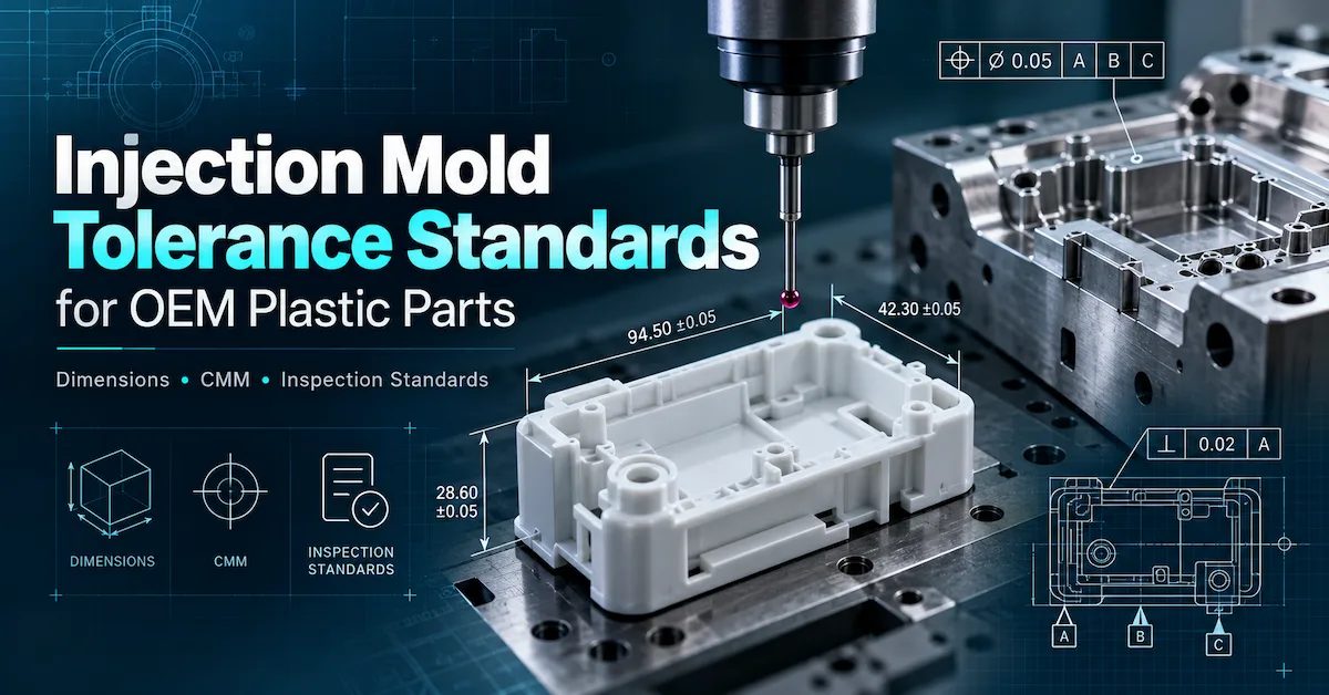
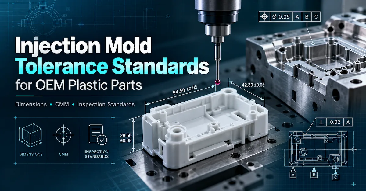
An injection mold tolerance is not a universal number that can be copied from one plastic project to another. The acceptable dimensional range for a molded part depends on product function, resin behavior, geometry, shrinkage, tooling design, molding conditions, measurement method and the drawing standard agreed between buyer and manufacturer.
For OEM buyers, the correct sequence is:
Define Function → Identify CTQs → Specify Tolerances → Review Manufacturability → Build Measurement Plan → Validate T0/T1 → Control Production
This distinction matters because “tight tolerance” is often used as a marketing phrase. A supplier may claim high precision, but the buyer still needs to know which dimensions are critical, what tolerance applies to each feature, how the part will be measured, and under what condition conformity will be decided.
A molded plastic housing, connector, automotive component, appliance part or industrial fitting may contain dozens of dimensions. Only some of them directly control fit, sealing, movement, alignment or assembly. Applying the tightest possible tolerance to every dimension can increase mold complexity, trial iterations, inspection cost and production risk without improving the finished product.
The more useful objective is functional dimensional control: use tighter requirements where the product genuinely needs them, and realistic general tolerances where the feature has lower functional importance.
1. Why Injection Mold Tolerance Is Not One Fixed Number
Buyers sometimes begin an RFQ by asking, “Can you hold ±0.01 mm?” That question is incomplete because it does not identify the feature, material, part size, geometry, measurement condition or functional reason for the requirement.
An injection mold tolerance must be evaluated at the molded-part level. The steel cavity may be machined with high precision, but the final plastic component also changes during filling, packing, cooling and release from the mold.
Two dimensions on the same part can behave differently. A short rigid boss may be relatively stable, while a long flat wall may be influenced by warpage. A glass-filled engineering polymer may show directional behavior that differs from an unfilled polymer. A dimension located across a parting line may require different consideration from a dimension formed entirely within one mold component.
This is why the buyer should distinguish among:
- Functional tolerance: required for product performance, fit or assembly.
- General tolerance: applied to features without individually stated direct tolerances.
- Direct tolerance: explicitly assigned to a specific dimension or geometrical requirement.
- Process capability: evidence that production can repeatedly stay within the required specification.
- Measurement capability: whether the inspection method can reliably evaluate the requirement.
These are related, but they are not interchangeable. A dimension can have a tight drawing tolerance while the production process is not yet capable of holding it consistently. Conversely, a capable process does not justify changing the drawing without engineering approval.
2. Which Tolerance Standards Matter for OEM Plastic Parts?
OEM buyers often encounter several standards in dimensional-control discussions. They do different jobs. A plastics tolerance standard does not replace a GD&T drawing language, and a CMM performance standard does not tell the designer what the product tolerance should be.
| Standard / Framework | Main Role | OEM Buyer Use |
|---|---|---|
| ISO 20457:2026 | Dimensional and geometrical tolerances and acceptance conditions for plastic moulded parts | Useful when defining realistic plastic-part tolerances and acceptance rules. |
| ISO 8015:2011 | Fundamental principles of ISO Geometrical Product Specifications | Supports interpretation of GPS requirements on technical product documentation. |
| ASME Y14.5-2018 (R2024) | GD&T symbols, definitions and drawing interpretation | Relevant when the OEM drawing uses ASME GD&T conventions. |
| ISO 14253-1:2017 | Decision rules for conformity or nonconformity using measurement results and uncertainty | Important when measurement results are close to specification limits. |
| ISO 10360 series | Acceptance and reverification requirements for coordinate measuring systems | Relevant to CMM system performance; it does not define the molded-part tolerance itself. |
ISO 20457 is particularly relevant because plastics do not behave like rigid metal parts. Its framework considers material behavior, molding shrinkage, process conditions, geometry, warpage and cooling effects when discussing technically achievable dimensional accuracy.
The standard should not be reduced to a copied tolerance table taken from the internet. If ISO 20457 is contractually required, the buyer and manufacturer should work from the applicable controlled standard and identify which tolerance concept applies to the actual product.
The same principle applies to ASME Y14.5. Writing “GD&T required” in an RFQ does not define the inspection plan. The drawing still needs clear datums, feature-control frames and functionally justified requirements.
3. Mold Machining Tolerance Is Not the Same as Molded-Part Tolerance
This is one of the most important distinctions in an injection mold tolerance discussion.
A moldmaker machines steel components. The OEM ultimately approves a plastic part. Between those two events, the polymer melts, flows through the cavity, packs, cools, shrinks and is ejected.
Therefore:
Precision mold machining is necessary for tight plastic-part control, but precise steel dimensions alone cannot guarantee the final molded dimension.
The mold designer may intentionally compensate cavity dimensions for expected molding shrinkage. The required compensation can depend on the exact resin grade, fiber content, flow direction, wall thickness, gate strategy and process conditions.
This is also why a customer drawing should specify the finished part requirement rather than asking the moldmaker to copy every plastic dimension directly into steel.
During DFM and mold design, the engineering team should establish how the plastic requirement translates into tooling geometry. During T0 and T1, the team then verifies whether the real molded result matches the intended condition.
If a molded dimension is outside tolerance, the correction may involve steel modification—but only after the team checks whether the deviation is really caused by tool geometry rather than process conditions, material behavior, cooling or measurement setup.
4. How Should OEM Drawings Define Injection Molding Tolerances?
A strong drawing does more than place a ± value beside every nominal dimension. It communicates which features matter, how they relate to one another, and how they should be inspected.
Define Critical-to-Quality Features
Start with dimensions that directly affect product performance. These commonly include:
- Mounting-hole location
- Boss position and height
- Connector alignment
- Sealing interfaces
- Snap-fit geometry
- Bearing or shaft interfaces
- Mating surface position
- Gap and clearance dimensions
- Features controlling final assembly
These features usually deserve more attention than dimensions with little effect on function.
Use Datums to Communicate Design Intent
A coordinate measurement is only useful if the part is aligned correctly. Datums tell the supplier which surfaces or features establish the reference system for inspection.
Without clear datum strategy, two inspection teams can measure the same plastic part differently. This becomes especially important for housings, irregular components, thin-wall parts and assemblies where the free-state shape can move slightly depending on how the component is supported.
Separate Reference Dimensions From Acceptance Dimensions
Not every displayed dimension should become a rejection criterion. Reference information helps communicate geometry but should not accidentally become another independent tolerance requirement unless that is truly the design intent.
Avoid Blanket Tight Tolerances
A title block that places one unusually tight default tolerance on every unspecified plastic dimension can create unnecessary manufacturing difficulty. Functionally important features should receive justified direct tolerances; less critical geometry can use an appropriate general-tolerance approach.
Need a Custom Mold for Controlled Plastic-Part Dimensions?
DX Molding's current plastic injection mold page lists support for custom 2D/3D designs, precision machining and a published mold tolerance range of ±0.01–±0.03 mm. Final part tolerances should still be reviewed against the actual resin, geometry and application.
Review Plastic Injection Mold Capabilities →5. What Factors Change Injection Molding Tolerances?
When an OEM team finds dimensional variation, the first reaction should not be to blame the CMM or cut the mold immediately. Several mechanisms can change the final molded geometry.
Material and Shrinkage
Different polymers shrink differently, and the same polymer family can contain multiple grades with different shrinkage behavior. Fillers, reinforcement, pigments and material conditioning can also affect dimensional behavior.
For this reason, the exact or candidate production resin should be defined before the mold designer finalizes shrinkage compensation for tight-tolerance features.
Part Geometry
Uniform geometry generally behaves more predictably than abrupt thickness changes. Thick bosses, ribs, deep sections, long flat walls and asymmetric shapes can create different cooling and shrinkage patterns.
A tight injection mold tolerance on a long, flexible plastic wall may therefore require more engineering attention than the same numeric tolerance on a short rigid feature.
Gate and Filling Pattern
Gate location controls how polymer enters the cavity. Flow direction affects pressure distribution, weld-line position, fiber orientation in reinforced materials and the way different areas pack.
Changing the gate strategy can therefore alter dimensional behavior as well as cosmetic results.
Packing and Holding
Packing compensates for material contraction while the gate remains effective. Inadequate or inconsistent packing may contribute to dimensional drift, sinks or different shrinkage behavior between areas of the part.
Cooling
Uneven cooling can produce differential shrinkage and warpage. Cooling-channel design, mold temperature and local wall thickness all interact.
A part can therefore meet a nominal size while still failing flatness, profile or assembly because the overall shape has distorted.
Ejection and Part Release
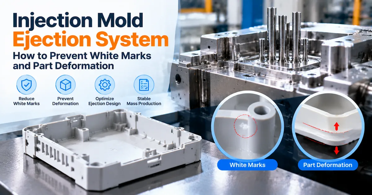
A molded part can deform during ejection if it sticks, lacks adequate draft or requires excessive release force. The inspection team should determine whether the measured condition represents the true molded geometry or deformation introduced during removal.
Conditioning and Moisture
Some polymers can change dimension after molding because of moisture absorption or thermal conditioning. If the application is sensitive, the buyer should define when the part is measured and whether conditioning is required before inspection.
6. How Tight Should an OEM Plastic-Part Tolerance Be?
The right answer is: as tight as the product function requires, but not tighter without a reason.
This function-first approach reduces unnecessary tooling and inspection burden.
| Feature Type | Typical Engineering Question | Recommended Approach |
|---|---|---|
| Decorative non-mating surface | Does this dimension affect fit or appearance? | Avoid excessive dimensional control if function does not require it. |
| Mounting hole | Must it align with another component? | Control size and location relative to functional datums. |
| Snap fit | What engagement and retention does assembly require? | Define the functional geometry and validate actual assembly. |
| Sealing interface | Which dimensions control seal compression or contact? | Identify CTQs and define inspection accordingly. |
| Large flat housing | Does warpage affect gap, flush or assembly? | Evaluate profile/flatness and assembly, not only overall length and width. |
| Connector interface | Does position control mating or electrical access? | Use functional datum relationships and repeatable measurement. |
This is also why tolerance discussions should happen before quotation is finalized. Tighter CTQs may influence machining strategy, cavity construction, cooling design, inspection equipment, fixtures, mold trials and the number of engineering iterations.
If a quotation does not mention an unusually tight tolerance that appears on the drawing, ask whether the supplier has actually reviewed it.
7. CMM Inspection: What Does It Actually Prove?
A coordinate measuring machine is valuable for evaluating complex geometry, positional relationships, profiles and precision interfaces. But CMM inspection is a measurement method, not a guarantee of part quality.
A CMM can produce a highly detailed report and still give misleading results if the inspection strategy is wrong.
Date Alignment
The measurement program must establish the part according to the drawing's intended datum system. Changing the alignment can materially change reported feature positions or profiles.
Fixturing
Plastic parts may flex. A fixture that forces the component into shape can produce a different result from a free-state measurement. The buyer and supplier should agree whether a feature is measured free, supported or restrained according to the design requirement.
Part Condition
Define when parts are inspected after molding and whether the material requires conditioning. Mixing freshly molded samples with stabilized parts can distort comparison data.
Sampling and Cavity Identification
For a multi-cavity mold, identify the cavity associated with each measured part. Combining all measurements without cavity identity can hide a cavity-specific problem.
Measurement Uncertainty
When a measured value is very close to a specification limit, measurement uncertainty can become important to the acceptance decision. ISO 14253-1 provides decision rules for proving conformity or nonconformity with specifications while accounting for measurement uncertainty.
This is especially relevant when buyers are working with very tight injection molding tolerances. If the required tolerance is close to the practical capability of the measurement system, inspection disagreements become more likely.
Need Dimensional Inspection and CMM Support?
DX Molding's published technical support includes T0/T1/T2 reports, full dimensional inspection with CMM data, critical-dimension control and CPK-related capability analysis.
Review Engineering & Inspection Support →8. Which Measurement Method Should Be Used?
The inspection method should be selected according to the feature and tolerance—not simply according to which equipment looks most sophisticated.
| Measurement Method | Useful For | Main Limitation / Check |
|---|---|---|
| Caliper | General external/internal dimensions where suitable | Operator force, access and feature geometry can affect results. |
| Micrometer | Suitable controlled thickness or diameter measurements | Contact force and plastic deformation need consideration. |
| Height gauge / surface plate | Height and referenced feature checks | Part support and datum setup must be consistent. |
| CMM | Complex positions, profiles and datum-related geometry | Programming, alignment, fixturing and uncertainty must be controlled. |
| Functional gauge | Fast pass/fail evaluation of selected functional interfaces | Gauge design and calibration must represent the actual requirement. |
| Assembly check | Verifying real fit with mating components | Does not replace dimensional data when numeric control is required. |
For important projects, it is often useful to combine dimensional measurement with a functional assembly check. The CMM may confirm feature location while the assembly verifies that the entire tolerance relationship works in practice.
9. Mold Tolerance vs Part Tolerance: What Should the RFQ Say?
An RFQ should focus on the finished plastic requirement and identify any tooling-specific expectations separately.
Instead of writing:
“Injection mold tolerance must be ±0.01 mm.”
a stronger RFQ might state:
“Feature A position is a CTQ and must meet the controlled drawing requirement after the agreed conditioning period. Supplier to review manufacturability, proposed measurement method and expected production capability before tooling release.”
This wording connects the requirement to the finished part and asks the supplier to confirm whether it is technically realistic.
For the mold itself, the quotation can separately define expectations for core/cavity machining, inserts, fitting, parting-line condition, shut-offs, slides and other critical tooling features.
DX Molding's current plastic injection mold page publicly lists a tolerance range of ±0.01 mm to ±0.03 mm and states tight tolerance control up to ±0.01 mm. This should be interpreted as a general published tooling capability range—not a blanket guarantee that every molded dimension, material and geometry will achieve ±0.01 mm.
A project-specific tolerance review is still required.
10. How Should T0 and T1 Validate Injection Mold Tolerance?
The first mold trial converts the drawing requirement into real measurement data. T0 should identify whether the tooling and molding process are moving toward the approved dimensions. T1 should verify agreed corrections.
This page does not repeat the entire trial-approval workflow covered in the T0 Mold Trial Guide. For tolerance control, the important points are:
- Confirm the correct drawing revision.
- Use the intended resin or clearly identify any substitute.
- Define the measurement condition.
- Identify samples by cavity where relevant.
- Measure CTQs using the agreed method.
- Document the actual deviation rather than only writing “NG.”
- Investigate whether the cause is tooling, process, material or measurement.
- Repeat the same controlled check after modification.
If T0 shows that a hole location is outside tolerance, the team should not simply move the steel by the measured error without further analysis. The actual deviation may include part shrinkage, fixture alignment or warpage.
After the correction, T1 should use the same acceptance basis so the engineering team can compare the result directly.
11. Why One Good Sample Does Not Prove Production Capability
Sample approval answers one question: can the tool produce parts that meet the defined requirements under the trial condition?
Production capability answers a different question: can the process repeatedly produce acceptable parts over time?
This distinction matters for tight injection mold tolerance requirements.
A single T1 sample can be within specification while later production drifts because of:
- Material-lot variation
- Mold-temperature variation
- Packing variation
- Cooling changes
- Machine condition
- Cavity imbalance
- Tool wear
- Measurement variation
For dimensions that are truly critical, the quality plan may include first-article inspection, periodic dimensional checks, cavity-level control and process-capability analysis such as CPK where appropriate and contractually required.
CPK should not be used as a decorative number in a supplier presentation. The buyer needs to understand which dimension is being analyzed, how much production data is included, whether the process is stable, and whether the measurement method is capable of supporting the calculation.
DX Molding's published support page lists a control plan for critical dimensions with CPK capability analysis as part of its production and process support. The exact requirement should still be defined for the individual OEM project.
For broader quality-control planning, the related Injection Mold Quality Guide covers quality gates from DFM through production.
12. Tolerance Stack-Up in Injection Molded Assemblies
Many OEM failures occur even when individual dimensions appear acceptable because several component variations combine at the assembly level.
A housing may contain:
- Plastic base dimensions
- Cover dimensions
- PCB hole locations
- Connector positions
- Fastener clearances
- Seal or gasket compression requirements
A conventional rigid-body tolerance calculation can become less representative when flexible plastic parts deform or warp. ISO 20457 specifically recognizes the different behavior of molded plastics compared with metals.
For this reason, OEM teams should combine tolerance analysis with real assembly validation. The engineering drawing defines the acceptance requirements, while sample testing confirms whether the complete system behaves as expected.
When a stack-up problem occurs, do not automatically tighten every component tolerance. First identify which dimensions contribute most strongly to the functional problem and which feature can be controlled economically.
13. How to Write a Better Tolerance RFQ
A tolerance-focused RFQ should give the mold supplier enough information to assess feasibility before the tool is quoted and manufactured.
| RFQ Input | Why It Matters |
|---|---|
| Controlled 2D drawing | Defines dimensions, tolerances, datums and GD&T requirements. |
| 3D CAD | Defines current geometry for DFM and mold design. |
| Exact or candidate resin | Supports shrinkage and dimensional-risk review. |
| CTQ list | Shows which dimensions deserve priority. |
| Assembly information | Reveals tolerance stack-up and interface risks. |
| Measurement requirements | Defines CMM, gauge, fixture or other inspection expectations. |
| Conditioning requirement | Controls when and how dimensional acceptance is performed. |
| Annual quantity | Supports mold construction and production-control planning. |
| Capability-data requirement | Clarifies whether CPK or other production evidence is required. |
A supplier should raise questions when a tolerance appears unusually demanding for the material, geometry or measurement method. That is not resistance to quality; it is part of engineering review.
The better commercial question is not “Can you make everything ±0.01 mm?” It is:
“Which dimensions require tight control, what manufacturing risks affect them, how will they be measured, and what evidence will demonstrate repeatable compliance?”
14. How DX Molding Supports Dimensional-Control Projects
DX Molding's current public plastic-injection-mold page lists custom plastic injection molds using P20, H13, S136 or custom steel, single- and multi-cavity configurations, hot or cold runner systems, and a published tolerance range of ±0.01 mm–±0.03 mm.
Its technical-support page also lists:
- DFM analysis
- Material and shrinkage consultation
- Mold flow analysis
- Cavity-layout planning
- Cooling optimization
- CNC and EDM manufacturing support
- T0/T1/T2 mold trial reporting
- Full dimensional inspection with CMM data
- Critical-dimension control
- CPK capability analysis support
These are useful capabilities for OEM projects where dimensional control is important. However, they do not mean that every plastic part can automatically be manufactured to the narrowest published value.
Actual injection molding tolerances should be reviewed against the part size, feature type, resin, geometry, mold layout, production conditions and inspection method.
For projects requiring broader precision-manufacturing considerations, the High Precision Mold Manufacturer Guide explains how DFM, machining, cooling, material behavior and process control interact. This page remains focused specifically on tolerance definition and dimensional acceptance so the two articles serve different search intent.
15. OEM Injection Mold Tolerance Approval Checklist
Drawing
- Current product revision identified
- CTQs defined
- Datums defined
- Direct and general tolerances distinguished
- GD&T standard identified where applicable
Manufacturability
- Resin identified
- Shrinkage reviewed
- Geometry and wall thickness reviewed
- Gate and cooling risks reviewed
- Tight tolerances justified by function
Inspection
- Measurement method defined
- Part conditioning defined where necessary
- Fixture / support method defined
- Cavity identity retained where required
- CMM datum strategy matches the drawing
Validation & Production
- T0 measurements recorded
- Corrections are traceable
- T1 repeats the same controlled inspection
- Approved sample and revision identified
- Production monitoring plan defined for CTQs
- Capability-data requirements defined where applicable
Frequently Asked Questions
1. What is injection mold tolerance?
Injection mold tolerance usually refers to the allowable dimensional variation associated with a molded plastic part or tooling requirement. For OEM projects, the finished-part tolerance should be defined on the controlled product drawing and reviewed against resin, geometry, molding behavior and measurement capability.
2. Is ±0.01 mm a standard injection molding tolerance?
No universal ±0.01 mm tolerance applies to every injection molded part. Feasibility depends on the feature, part size, resin, geometry, tooling, process and measurement method. DX Molding's current mold page lists a published tooling tolerance range of ±0.01–±0.03 mm, but project-specific part requirements still need engineering review.
3. Which standard applies to plastic injection molding tolerances?
ISO 20457:2026 specifically addresses dimensional and geometrical tolerances and acceptance conditions for plastic moulded parts. The applicable contractual standard should be identified on the drawing or project documentation.
4. What is the difference between mold tolerance and molded-part tolerance?
Mold tolerance relates to tooling dimensions and manufacturing control. Molded-part tolerance applies to the finished plastic component. The two are connected, but material shrinkage, processing, cooling and warpage mean they are not numerically identical.
5. When should CMM inspection be used?
CMM inspection is useful for complex dimensional relationships, feature position, profile and datum-based geometry. The inspection method should be selected according to the feature and required tolerance rather than using CMM automatically for every dimension.
6. Can CMM inspection guarantee part quality?
No. CMM accuracy depends on the machine, program, probing strategy, datum alignment, fixture, part condition and measurement uncertainty. CMM data is useful evidence only when the inspection system is properly controlled.
7. Why do injection molded dimensions change after molding?
Material shrinkage, cooling, warpage, moisture conditioning, packing, mold temperature, geometry and ejection can influence final dimensions. The importance of each factor depends on the actual resin and part design.
8. Should every dimension have a tight tolerance?
No. Tighter tolerances should be concentrated on features that control function, assembly, sealing, positioning or another genuine product requirement. Unnecessary tight tolerances can add manufacturing and inspection cost without improving product performance.
9. How should multi-cavity molds be inspected?
For critical dimensions, samples should remain traceable to their cavity where practical. Cavity-level data helps distinguish a systematic process issue from a cavity-specific dimensional problem.
10. What should I send to DX Molding for a tolerance-sensitive project?
Send the current 2D drawing, 3D CAD, resin specification, expected quantity, CTQ dimensions, assembly information, measurement requirements and application details. Clearly identify any dimensions that require special inspection or capability data.
Conclusion
A reliable injection mold tolerance strategy starts with function, not the smallest possible ± value. OEM buyers should define CTQs, use an appropriate plastics tolerance framework, control datums and measurement conditions, verify dimensions through CMM or other suitable methods, and use T0/T1 data to confirm that the tooling and process can meet the requirement. Tight tolerances create value only when they are measurable, manufacturable and necessary for the finished product.
Discuss Your Tolerance Requirements →