Why Does DFM Matter When Choosing an Injection Mold Supplier?
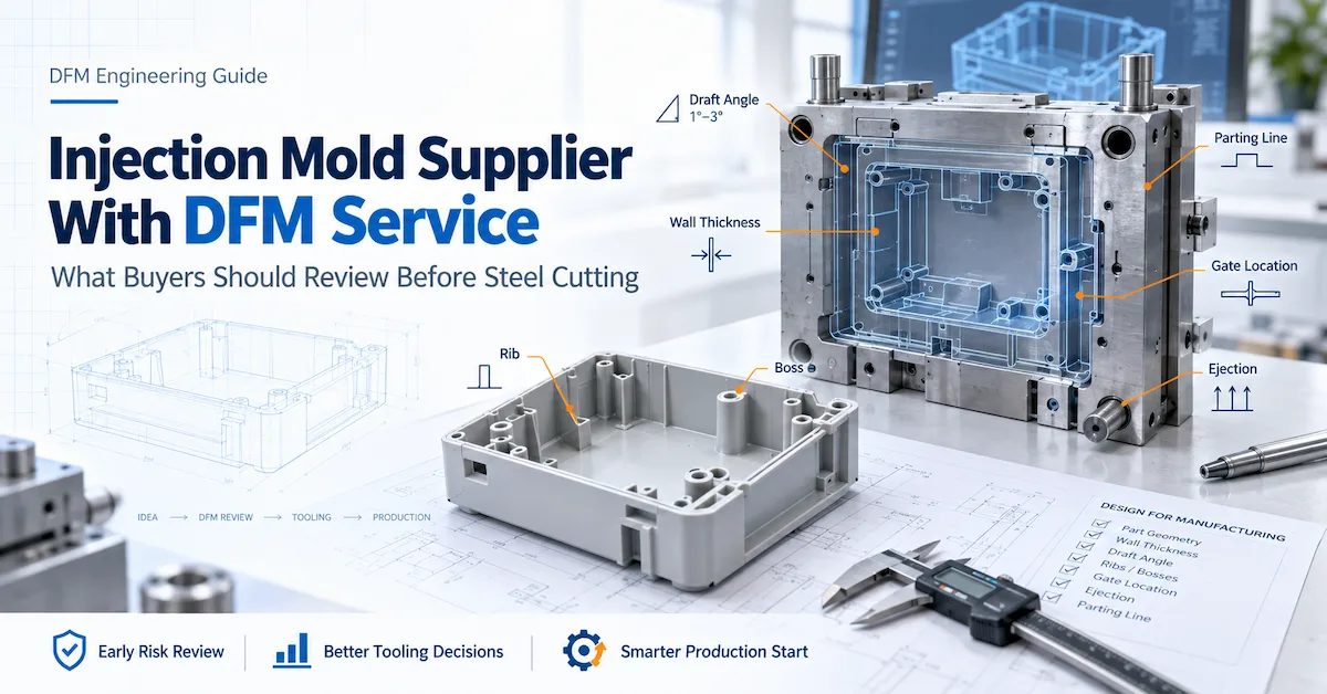
Choosing an injection mold supplier with DFM service is not simply about receiving a report before mold manufacturing.
The real value of Design for Manufacturing is identifying where product geometry, material, tooling structure, molding behavior, assembly requirements, and cosmetic expectations may conflict before those conflicts become expensive steel changes.
A mold supplier can manufacture exactly what appears in a CAD model and still deliver a difficult production tool if the design was never challenged from a manufacturing perspective.
For OEM buyers, DFM should therefore answer a practical question:
What needs to be confirmed, changed, or accepted before this part is released for tooling?
DX Molding includes DFM and manufacturing-risk assessment within its engineering and production support, alongside material review, mold engineering, trial molding, inspection, and production support.
What Is DFM in an Injection Mold Project?
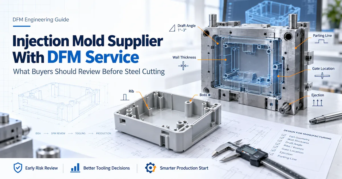
DFM stands for Design for Manufacturing.
In an injection molding project, it is the engineering review that connects the product design to the realities of mold construction and repeatable plastic production.
A useful DFM review may evaluate:
-
Mold opening direction
-
Draft angle
-
Wall thickness
-
Ribs
-
Bosses
-
Fillets and radii
-
Undercuts
-
Side actions
-
Parting-line location
-
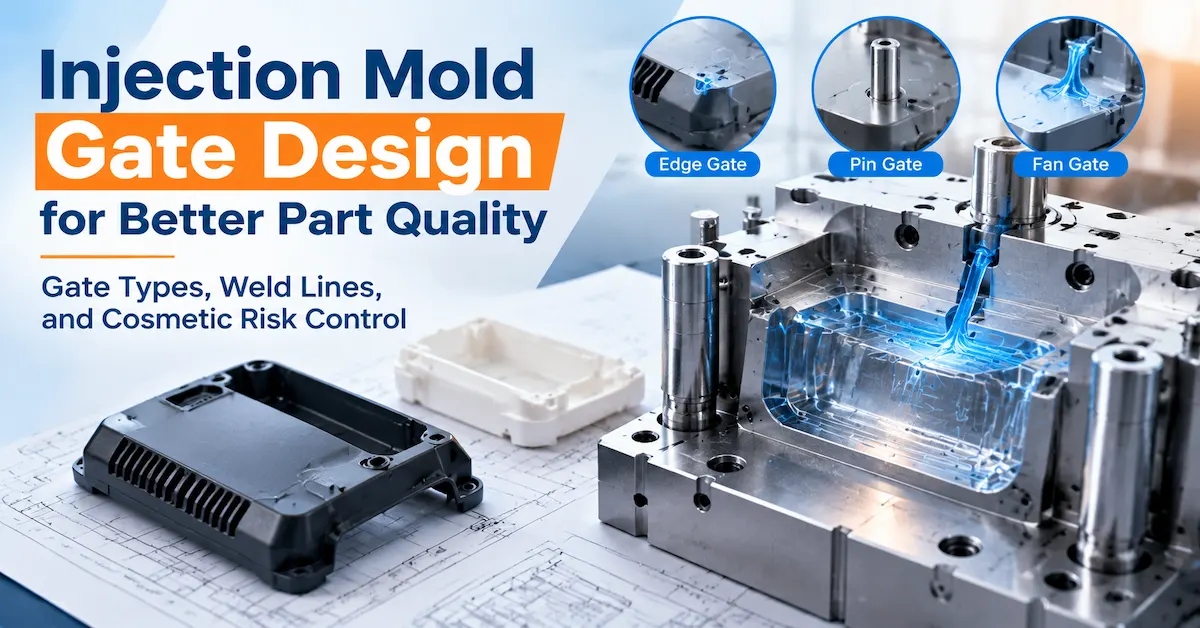
Gate location
-
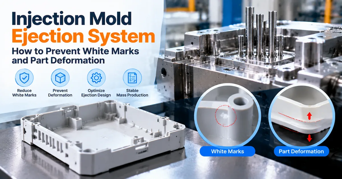
Ejection
-
Material shrinkage
-
Sink-mark risk
-
Warpage risk
-
Weld-line considerations
-
Cosmetic surfaces
-
Assembly interference
The goal is not merely to prove that a part can be molded.
The better goal is to determine whether the proposed design can be molded reliably, economically, and repeatedly at the intended production volume.
Why Should DFM Happen Before Steel Cutting?
Once mold steel has been machined, design changes become more difficult.
Some modifications can be handled by removing additional steel. Others may require welding, replacing inserts, rebuilding mechanisms, changing gates, or even revising major mold components.
That is why the sequence matters:
Product Requirements → DFM → Design Decisions → Mold Design → Steel Cutting
not:
Product CAD → Steel Cutting → Discover Problems → Modify Tool
Early Changes Are Usually Easier to Control
Before machining, changing a rib, boss, draft angle, or undercut may only require a CAD revision and engineering approval.
After machining, the same change may influence:
-
Core and cavity steel
-
Slides or lifters
-
Cooling channels
-
Electrodes
-
Ejector positions
-
Tooling schedule
-
Trial timing
A DFM review is therefore most valuable before the mold structure is frozen.
What Should an Injection Mold Supplier With DFM Service Actually Review?
Not every DFM report has the same engineering depth.
Some suppliers provide a few screenshots showing draft and parting lines. Others connect each observation to tooling structure, molding behavior, appearance, assembly, and production risk.
Buyers should understand what is actually included.
Draft Angle and Part Release
Draft allows molded surfaces to release from the core or cavity.
Insufficient draft can increase:
-
Release resistance
-
Drag marks
-
Scuffing
-
Ejection force
-
Part deformation
-
Tool wear
Draft Should Be Reviewed With Surface Finish
A smooth surface and a deeply textured surface do not create identical release conditions.
For visible or textured products, the DFM discussion should consider:
-
Surface direction
-
Texture
-
Depth
-
Mold opening direction
-
Cosmetic restrictions
-
Ejection strategy
A recommendation such as “add 1° draft” is less useful than an explanation of why that surface needs additional release allowance.
Wall Thickness and Part Stability
Wall thickness affects more than material consumption.
It can influence:
-
Filling
-
Cooling
-
Shrinkage
-
Sink marks
-
Warpage
-
Cycle time
-
Part stiffness
A useful DFM review should identify unusually thick or thin areas and explain whether the transition may create molding problems.
Uniformity Matters More Than One Universal Number
There is no single wall-thickness value suitable for every resin and every component.
The correct approach depends on:
-
Material
-
Part size
-
Flow length
-
Structural requirement
-
Appearance
-
Assembly
-
Moldability
The DFM engineer should therefore review geometry in the context of the actual product rather than applying one generic rule.
Ribs and Bosses
Ribs and bosses often look simple in CAD, but they can influence both structure and appearance.
They are frequently used for:
-
Stiffness
-
PCB support
-
Screw assembly
-
Component location
-
Alignment
-
Snap assembly
However, heavy ribs or bosses positioned behind cosmetic walls can increase sink-mark risk.
Review Internal Features Against External Surfaces
A useful DFM analysis should not inspect a boss in isolation.
It should also ask:
-
What surface is behind the boss?
-
Is that surface visible?
-
How thick is the surrounding wall?
-
Is structural strength critical?
-
Can the geometry be optimized?
The correct solution may involve geometry changes rather than simply adjusting molding pressure later.
Undercuts, Slides, and Lifters
Undercuts can significantly change mold complexity.
Typical examples include:
-
Side holes
-
Hooks
-
Clips
-
Locking features
-
Recesses
-
Reverse geometry
These features may require:
-
Slides
-
Lifters
-
Side cores
-
Inserts
-
Alternative parting strategies
Each additional moving mechanism may affect:
-
Mold cost
-
Mold size
-
Manufacturing time
-
Maintenance
-
Wear
-
Long-term stability
Ask Whether the Undercut Is Functionally Necessary
One of the highest-value DFM questions is:
Can this feature be redesigned without changing product function?
If yes, the product may become easier to tool and manufacture.
If no, the supplier should deliberately engineer the required mold mechanism.
Parting-Line Location
Parting lines are not only mold-design details.
They can influence:
-
Appearance
-
Flash control
-
Shut-off design
-
Dimensional consistency
-
Assembly
-
Secondary finishing
For cosmetic parts, the buyer should define where a parting line is acceptable before mold design is approved.
A supplier should not decide this only after the tool structure has been finalized.
Gate Location
Gate location affects how plastic enters the cavity.
It may influence:
-
Filling pattern
-
Weld lines
-
Air traps
-
Packing
-
Appearance
-
Shrinkage
-
Warpage
-
Gate vestige
The best location is not always the least visible location.
A hidden gate that creates poor filling or dimensional instability may be a worse engineering decision than a controlled gate mark in an acceptable zone.
DX Molding's technical support workflow includes gate-location and mold-flow-related evaluation as part of early manufacturing support.
Ejection Strategy
After cooling, the molded part must leave the tool without damage.
Potential problems include:
-
Part sticking
-
Whitening
-
Distortion
-
Ejector marks
-
Cracking
-
Dragging
-
Uneven release
DFM should identify surfaces where ejection may be difficult.
Cosmetic and Functional Areas Need Different Treatment
An ejector mark may be acceptable on a hidden structural surface but unacceptable on a customer-visible face.
The buyer should identify these areas before mold design.
Sink-Mark Risk
Sink marks commonly appear where local material thickness increases.
Typical risk areas include:
-
Boss bases
-
Thick ribs
-
Material accumulations
-
Transitions
-
Reinforced corners
DFM can identify these zones before tooling.
The solution may involve:
-
Geometry optimization
-
Rib changes
-
Boss changes
-
Wall transition changes
-
Gate strategy
-
Process considerations
The supplier should avoid presenting molding parameters as the only solution when the root cause is product geometry.
Warpage Risk
Warpage can come from several interacting factors:
-
Uneven wall thickness
-
Uneven cooling
-
Material shrinkage
-
Fiber orientation
-
Gate location
-
Part geometry
-
Packing conditions
This makes warpage a good example of why product design and mold design cannot always be reviewed separately.
For higher-risk components, a supplier may combine DFM with mold-flow-related analysis before finalizing the tooling strategy.
Assembly Interference
A molded part can pass its own dimensions and still fail in the complete product.
DFM should therefore review important mating features where information is available.
Examples include:
-
Snap fits
-
Screw bosses
-
Connectors
-
Alignment features
-
Sealing surfaces
-
PCB locations
-
Metal inserts
-
Adjacent housings
The buyer should provide mating-part information for critical assemblies whenever possible.
What Does a Useful DFM Report Look Like?
A useful report should help the buyer make decisions.
It should not simply demonstrate that the supplier has opened the CAD file.
A practical format may contain:
| DFM Item | Supplier Observation | Possible Risk | Decision Needed |
|---|---|---|---|
| Draft | Low draft on side wall | Difficult release | Add draft or accept risk |
| Boss | Heavy boss behind A-surface | Sink mark | Reduce boss mass |
| Undercut | Side clip requires action | Higher tool complexity | Keep clip or redesign |
| Parting line | Crosses visible surface | Cosmetic line | Relocate or approve |
| Gate | Current position affects surface | Visible vestige | Review gate zone |
| Wall transition | Large thickness change | Sink/warpage | Smooth transition |
| Ejection | Limited ejector area | Distortion risk | Revise geometry or layout |
The report should clearly separate:
Observation → Engineering Risk → Recommendation → Buyer Decision
That structure makes approval easier and creates a record of why the design was released.
“Free DFM” vs Useful DFM Service
“Free DFM” is common language in the mold industry.
However, buyers should evaluate the content rather than the label.
A Basic DFM May Only Show
-
Mold opening direction
-
Parting line
-
Draft
-
Gate
-
Obvious undercuts
That may be sufficient for a simple product.
A More Detailed Review May Include
-
Wall-thickness risk
-
Ribs and bosses
-
Cosmetic concerns
-
Assembly
-
Ejection
-
Sink
-
Warpage
-
Moving mechanisms
-
Material considerations
-
Mold-flow-related issues
-
Production-volume implications
The appropriate depth should match the complexity and risk of the project.
A simple cap does not need the same analysis as a large enclosure with multiple clips, cosmetic surfaces, precision interfaces, and a long production program.
What Information Does the Supplier Need Before DFM?
DFM quality depends partly on the information supplied by the buyer.
The CAD model alone cannot explain every project requirement.
Prepare the Following Where Available
| Buyer Input | Why It Helps DFM |
|---|---|
| 3D CAD | Defines complete geometry |
| Controlled 2D drawing | Identifies critical dimensions |
| Resin or candidate material | Supports shrinkage and process review |
| Annual volume | Supports tooling strategy |
| Cosmetic surfaces | Controls parting, gates and ejection |
| Texture requirement | Influences release and finish |
| Mating components | Supports assembly review |
| Product application | Defines functional priorities |
| Target mold life | Supports tool construction |
| Mold destination | Supports machine compatibility |
| Existing prototype | Provides design context |
For an early-stage project, some items may still be unresolved.
That is acceptable.
They should simply be marked as open engineering items instead of being replaced with assumptions.
How Does DFM Affect Mold Cost?
DFM itself is not primarily a cost-cutting exercise.
Its purpose is to make manufacturing risk visible.
Sometimes a DFM recommendation reduces tooling complexity.
For example, removing an unnecessary undercut could eliminate a slide.
In other cases, DFM may reveal that additional tooling complexity is necessary to meet the functional requirement.
Cost Can Be Influenced by
-
Slides
-
Lifters
-
Inserts
-
Cavity count
-
Tool steel
-
Hot runner
-
Cooling complexity
-
Tight tolerance
-
Cosmetic requirements
-
Mold-flow analysis
-
Validation
-
Inspection
-
Engineering changes
The cheapest DFM outcome is not always the correct one.
The target should be:
Appropriate tooling cost + stable part quality + manageable production risk
DFM Should Connect to Mold Design
DFM should not be a report that disappears after customer approval.
Its decisions should influence the actual mold.
For example:
DFM Decision: Maintain side undercut
Mold Consequence: Add slide mechanism
DFM Decision: Protect cosmetic surface
Mold Consequence: Relocate gate and ejectors
DFM Decision: Critical assembly dimension
Mold Consequence: Review shrinkage, steel-safe strategy, and inspection
DFM Decision: High annual volume
Mold Consequence: Review cavity strategy, cooling, steel, and maintenance
DX Molding's injection mold design guide explains additional decisions buyers should review before mold machining begins.
Where Does Mold Flow Fit Into DFM?
DFM and mold flow are related but not identical.
DFM Reviews Product and Manufacturing Logic
It asks questions such as:
-
Is the geometry moldable?
-
Where are the undercuts?
-
Is draft sufficient?
-
Where should the parting line be?
-
Where are sink risks?
-
Can the part eject?
Mold Flow Evaluates Molding Behavior
Depending on the analysis, it may evaluate:
-
Filling
-
Packing
-
Cooling
-
Warpage
-
Weld lines
-
Air traps
-
Gate location
Not every simple plastic part requires extensive simulation.
The need should be determined by project complexity and manufacturing risk.
What Happens After DFM Approval?
DFM approval is not the end of engineering.
It is the point where the team should have enough information to move into controlled mold design.
A typical project sequence may be:
1. Requirement Review
Confirm:
-
CAD
-
Material
-
Quantity
-
Tolerances
-
Appearance
-
Application
-
Production strategy
2. DFM Review
Identify manufacturing risks and unresolved decisions.
3. Buyer Approval
Approve agreed geometry changes and risk decisions.
4. Mold Design
Develop:
-
Core and cavity
-
Parting
-
Gates
-
Runner
-
Cooling
-
Ejection
-
Slides/lifters
-
Mold base
5. Mold Manufacturing
Typical operations can include:
-
CNC
-
EDM
-
Finishing
-
Polishing
-
Fitting
-
Assembly
6. Trial Molding
Evaluate the tool and molded component.
7. Modification and Validation
Resolve remaining tooling or product issues.
8. Production or Mold Transfer
Release the approved mold for production.
DX Molding describes this broader process within its custom manufacturing services.
How Should Buyers Evaluate the Supplier's DFM Capability?
Do not judge DFM only by how attractive the PDF looks.
Evaluate whether the supplier can explain manufacturing cause and effect.
Ask These Questions
Why Are You Recommending This Change?
The supplier should connect the recommendation to:
-
Tool structure
-
Molding
-
Quality
-
Appearance
-
Assembly
-
Production stability
What Happens if We Do Not Make the Change?
This helps distinguish:
-
Mandatory manufacturing changes
-
Strong engineering recommendations
-
Optional improvements
Does This Change Affect Product Function?
The supplier should not optimize manufacturability while unintentionally damaging product performance.
Does This Change Affect Mold Cost?
A geometric change may:
-
Simplify tooling
-
Add moving mechanisms
-
Change cavity layout
-
Affect machining
-
Change maintenance needs
Can You Show the Before-and-After Geometry?
Visual comparison reduces miscommunication.
DX Molding's current engineering support includes formal DFM reporting and before/after design comparisons for relevant projects.
What Are the Warning Signs of Weak DFM Support?
An injection mold supplier with DFM service should do more than place colored arrows on a CAD screenshot.
Watch for these warning signs.
The Supplier Gives a Final Tooling Quote Before Understanding the Part
If the supplier does not ask about:
-
Material
-
Volume
-
Tolerance
-
Appearance
-
Assembly
-
Application
the quotation may be based on assumptions.
Every Recommendation Says “Customer Must Change”
A good DFM process should distinguish genuine manufacturing constraints from supplier preferences.
There Is No Explanation Behind Recommendations
“Change this feature” is weaker than:
“Changing this feature avoids a side action and simplifies mold maintenance.”
Cosmetic Requirements Are Ignored
Parting, gate, ejector, texture, and sink decisions can directly influence visible surfaces.
DFM Is Not Connected to the Final Tool Design
Approved DFM decisions should remain traceable through mold design.
Who Should Approve DFM Changes?
The supplier should recommend manufacturing changes, but buyer approval is still important.
Typical responsibility can be divided as follows:
| Decision | Buyer | Supplier | Joint Review |
|---|---|---|---|
| Product function | ✓ | ||
| Cosmetic requirements | ✓ | ✓ | |
| DFM observations | ✓ | ||
| Tooling feasibility | ✓ | ||
| Product geometry change | ✓ | ||
| Mold structure | ✓ | ✓ | |
| Material alternative | ✓ | ||
| Critical tolerance | ✓ | ✓ | |
| Production release | ✓ | ✓ |
A supplier recommendation should not automatically become a product-design change without an approval record.
What Should Buyers Approve Before Steel Cutting?
Before tooling is released, confirm key items such as:
-
Approved CAD revision
-
Resin
-
Critical dimensions
-
Cosmetic surfaces
-
Draft decisions
-
Wall-thickness changes
-
Undercuts
-
Parting line
-
Gate concept
-
Mold structure
-
Cavity count
-
Runner system
-
Slides/lifters
-
Mold steel
-
Tool-life expectation
-
Trial requirements
-
Inspection requirements
-
Mold destination
For a more complete project-planning framework, buyers can also review DX Molding's plastic injection mold project guide.
How Should You Compare Two Suppliers Offering DFM?
Do not compare only whether both suppliers say “DFM included.”
Compare what they actually review.
| Evaluation Area | Supplier A | Supplier B |
|---|---|---|
| Draft review | Yes/No | Yes/No |
| Wall thickness | Yes/No | Yes/No |
| Ribs and bosses | Yes/No | Yes/No |
| Undercut analysis | Yes/No | Yes/No |
| Parting-line proposal | Yes/No | Yes/No |
| Gate discussion | Yes/No | Yes/No |
| Sink/warpage risk | Yes/No | Yes/No |
| Assembly review | Yes/No | Yes/No |
| Mold-flow support | Yes/No | Yes/No |
| Before/after geometry | Yes/No | Yes/No |
| Engineering explanation | Yes/No | Yes/No |
| Formal buyer approval | Yes/No | Yes/No |
The stronger supplier is not necessarily the one that identifies the most “problems.”
It is the supplier that identifies the right risks, explains them clearly, and converts approved decisions into a practical mold design.
Does DFM Guarantee a Problem-Free Mold?
No.
DFM reduces known and foreseeable manufacturing risk, but it cannot remove every variable from injection molding.
Actual production can still be influenced by:
-
Resin lot
-
Machine
-
Mold temperature
-
Melt temperature
-
Pressure
-
Packing
-
Cooling
-
Equipment condition
-
Environmental conditions
-
Product revisions
DFM should therefore be viewed as the first engineering risk-control stage, followed by mold design, machining, trial molding, dimensional validation, and production optimization.
What Should Be Checked During Mold Trials?
After the tool is built, the team should verify whether the DFM and mold-design decisions work in practice.
Trial checks may include:
-
Filling
-
Flash
-
Short shot
-
Sink
-
Warpage
-
Weld lines
-
Surface appearance
-
Ejection
-
Critical dimensions
-
Assembly
-
Process stability
DX Molding's engineering support process includes T0/T1/T2-related trial support, dimensional inspection, modification follow-up, and process optimization according to project requirements.
Should the Same Supplier Handle Tooling and Injection Molding?
It depends on the supply model.
Tooling + Production With One Supplier
This can simplify:
-
Process handover
-
Parameter control
-
Mold maintenance
-
Quality feedback
-
Engineering changes
DX Molding also provides plastic injection molding services for projects that continue into molded-part supply.
Tooling Followed by Mold Transfer
Other OEMs plan to move the mold to:
-
Their own plant
-
A nominated molder
-
A regional production partner
In this case, DFM should also consider the final production environment.
Machine and interface requirements should be discussed early rather than after the mold is finished.
What Should You Send for a DFM and Mold Quotation?
A well-prepared RFQ helps the supplier review the real project instead of pricing assumptions.
Prepare as much of the following as possible:
-
3D CAD / STEP file
-
2D drawing
-
Resin or candidate material
-
Annual production volume
-
Initial order quantity
-
Critical dimensions
-
Cosmetic surfaces
-
Texture requirement
-
Mating components
-
Application environment
-
Expected mold life
-
Mold destination
-
Machine information if relevant
-
Required reports
-
Project timeline
If the project is still early, explain which decisions remain open.
The supplier can then distinguish preliminary engineering assumptions from approved production requirements.
How DX Molding Supports DFM Before Tooling
DX Molding supports custom mold projects from engineering review through tooling, trials, and production.
Its technical support capabilities include DFM review for areas such as:
-
Draft
-
Wall thickness
-
Fillets
-
Undercuts
-
Side-core feasibility
-
Assembly interference
-
Sink risk
-
Warpage risk
The same project may also involve material review, mold-flow-related analysis, mold engineering, CNC/EDM processing, trial molding, dimensional inspection, and manufacturing support.
Buyers evaluating the complete supplier rather than only DFM can also use DX Molding's injection mold supplier selection checklist.
Injection Mold Supplier With DFM Service Evaluation Checklist
Before approving a supplier, ask:
-
Does the supplier review the complete product application?
-
Does the DFM explain risks, not only show geometry?
-
Are draft and wall thickness reviewed?
-
Are ribs and bosses evaluated against visible surfaces?
-
Are undercuts connected to mold complexity?
-
Are gate and parting-line decisions explained?
-
Are sink and warpage risks discussed?
-
Are assembly interfaces considered?
-
Are cosmetic requirements identified?
-
Can the supplier support mold-flow-related analysis if needed?
-
Are product changes controlled by revision?
-
Are DFM decisions transferred into mold design?
-
Are trial requirements defined?
-
Can inspection verify critical dimensions?
-
Is production or mold-transfer support available?
A clear answer to these questions makes supplier comparison more useful than simply asking whether “free DFM” is included.
Frequently Asked Questions
What Is DFM in Injection Molding?
DFM, or Design for Manufacturing, reviews a plastic part before tooling to identify geometry and manufacturing conditions that may affect mold design, molding stability, appearance, assembly, or production cost.
When Should DFM Be Completed?
Ideally, DFM should be completed and key changes approved before the mold design is finalized and before major steel machining begins.
Is DFM the Same as Mold Design?
No. DFM reviews the product's manufacturability. Mold design converts the approved product requirements into the actual tooling structure, including cores, cavities, runners, cooling, ejection, and mechanisms.
Is Mold Flow Analysis Part of DFM?
It can support DFM, but they are not identical. Mold flow focuses more specifically on filling, packing, cooling, warpage, weld lines, air traps, and related molding behavior.
Does Every Product Need Mold Flow Analysis?
Not necessarily. The decision should depend on product geometry, material, quality requirements, and manufacturing risk.
Can DFM Reduce Mold Cost?
Sometimes. DFM may identify unnecessary undercuts or other complexity. In other cases, it may reveal that additional tooling features are required to meet the product specification.
Who Should Approve DFM Changes?
The mold supplier can recommend changes, but changes that affect product geometry, function, appearance, or critical requirements should normally be approved through the buyer's engineering process.
What Files Are Needed for DFM?
A 3D CAD file is normally the starting point. A controlled 2D drawing, material information, cosmetic requirements, annual volume, assembly details, and critical tolerances make the review more useful.
Does a Good DFM Report Guarantee Production Quality?
No. DFM reduces early design and tooling risk, but production quality also depends on mold design, machining, trial validation, material, process conditions, maintenance, and quality control.
How Can I Request DFM Support From DX Molding?
Prepare your CAD, drawings, material, quantity, critical dimensions, appearance requirements, assembly conditions, and intended production plan. You can then contact DX Molding for a project-specific engineering and tooling review.
Conclusion
Choosing an injection mold supplier with DFM service should focus on the quality of engineering decisions—not whether a supplier simply offers a free report. Effective DFM should expose product, tooling, cosmetic, assembly, and production risks before steel cutting and connect approved decisions directly to mold design.
For a project-specific review, prepare your CAD, resin, annual volume, critical tolerances, surface requirements, assembly information, and production plan, then contact DX Molding for a DFM and tooling evaluation.